2NR-FE ENGINE MECHANICAL CYLINDER BLOCK INSPECTION
PROCEDURE

 1.INSPECT CYLINDER BLOCK FOR WARPAGE
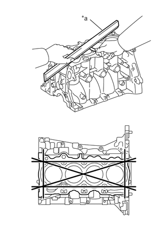
| *a | Precision Straightedge |
Using a precision straightedge and feeler gauge, check the surface which contacts the cylinder head gasket for warpage.
- Maximum warpage:
0.05 mm (0.00197 in.)
If the warpage is greater than the maximum, replace the cylinder block sub-assembly.
2.INSPECT CYLINDER BORE
Visually inspect the surface of the cylinder walls to make sure there are no scratches, etc.
If there are scratches, etc. on the cylinder walls, replace the cylinder block sub-assembly.
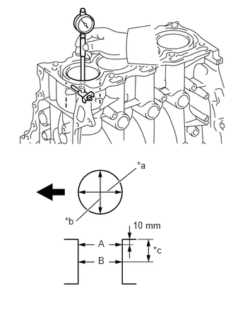
| *a | Axial Direction |
| *b | Thrust Direction |
| *c | Center |

|
Front |
Using a cylinder gauge, measure the cylinder bore diameter at the positions A and B in both thrust and axial directions.
- Reference value (new parts) diameter:
72.500 to 72.513 mm (2.8544 to 2.8548 in.)
- Maximum diameter:
72.633 mm (2.8596 in.)
If the inside diameter is greater than the maximum, replace the cylinder block sub-assembly
3.INSPECT PISTON
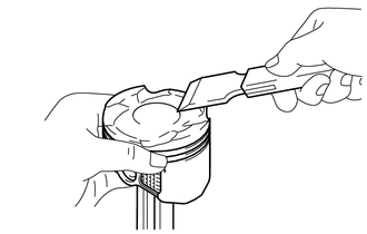
Using a gasket scraper, scrape off any carbon on the top of the piston.
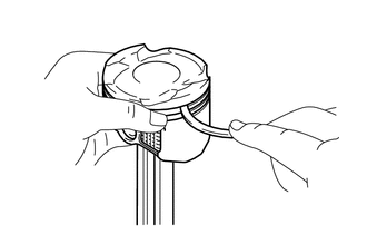
Using a groove cleaning tool or broken ring, clean the piston ring grooves.
Using a brush and solvent, thoroughly clean the piston.
- NOTICE:
-
Do not use a wire brush.
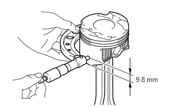
Using a micrometer, measure the piston diameter at right angles to the piston pin hole, and at a point 9.8 mm (0.386 in.) from the piston bottom.
- Reference value (new parts) piston diameter:
72.450 to 72.482 mm (2.8524 to 2.8536 in.)
If the diameter is not as specified, replace the piston with pin sub-assembly and connecting rod sub-assembly.
4.INSPECT PISTON OIL CLEARANCE
Subtract the piston diameter measurement from the cylinder bore diameter measurement to calculate the oil clearance.
- Reference value (new parts) oil clearance:
0.018 to 0.063 mm (0.0007 to 0.0025 in.)
- Maximum oil clearance:
0.117 mm (0.00461 in.)
If the piston oil clearance is greater than the maximum, calculate the oil clearance using the measured cylinder internal diameter and piston external diameter as well as the reference diameters (for new parts), and replace the piston with pin sub-assembly and connecting rod sub-assembly or cylinder block sub-assembly.
5.INSPECT RING GROOVE CLEARANCE
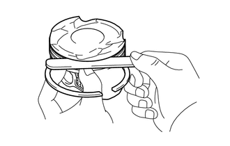
Using a feeler gauge, measure the ring groove clearance between piston ring set and wall of the ring groove.
- Standard Ring Groove Clearance:
Item Specified Condition No. 1 Compression Ring 0.02 to 0.07 mm (0.00079 to 0.00275 in.) No. 2 Compression Ring 0.02 to 0.06 mm (0.00079 to 0.00236 in.) Oil ring (Side Rail) 0.07 to 0.15 mm (0.00276 to 0.00591 in.)
If the ring groove clearance is not as specified, replace the piston ring set. If the ring groove clearance is still not as specified even with a new piston ring set, replace the piston with pin sub-assembly and connecting rod sub-assembly.
6.INSPECT PISTON RING END GAP
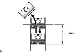
Using a piston, push the piston ring a little beyond the bottom of the piston ring travel, 50 mm (1.97 in.) from the top of the cylinder block sub-assembly.
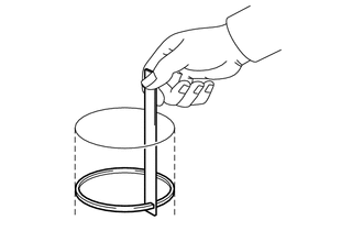
Using a feeler gauge, measure the end gap.
- Standard End Gap:
Item Specified Condition No. 1 Compression Ring 0.15 to 0.20 mm (0.00591 to 0.00787 in.) No. 2 Compression Ring 0.30 to 0.50 mm (0.01181 to 0.01969 in.) Oil ring (Side Rail) 0.10 to 0.40 mm (0.00394 to 0.01574 in.)
- Maximum End Gap:
Item Specified Condition No. 1 Compression Ring 0.48 mm (0.01890 in.) No. 2 Compression Ring 0.70 mm (0.02756 in.) Oil ring (Side Rail) 0.55 mm (0.02165 in.)
If the piston ring end gap is greater than the maximum, replace the piston ring set. If the piston ring end gap is greater than the maximum, even with a new piston ring set, replace the cylinder block sub-assembly.
7.INSPECT CONNECTING ROD THRUST CLEARANCE
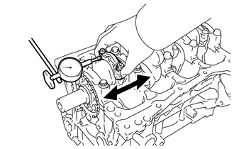
Using a dial indicator, measure the thrust clearance while moving the connecting rod back and forth.
- Standard thrust clearance:
0.1 to 0.5 mm (0.00394 to 0.01968 in.)
- Maximum thrust clearance:
0.5 mm (0.01968 in.)
If the thrust clearance is greater than the maximum, replace the connecting rod sub-assembly and piston with pin sub-assembly as necessary. If necessary, replace the crankshaft.
8.INSPECT CONNECTING ROD OIL CLEARANCE
Clean the crank pin and connecting rod bearing.
Remove the connecting rod cap.
Click hereEngine / Hybrid System>2NR-FE ENGINE MECHANICAL>CYLINDER BLOCK>DISASSEMBLY
Check the crank pin and connecting rod bearing for pitting and scratches.
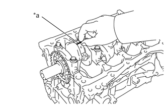
| *a | Plastigage |
Lay a strip of Plastigage across the crank pin.
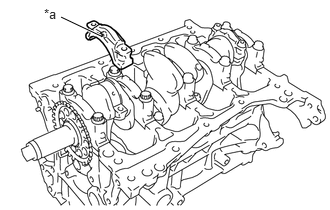
| *a | Front Mark |
Check that the front mark of the connecting rod cap is facing forward.
Install the connecting rod cap.
Click hereEngine / Hybrid System>2NR-FE ENGINE MECHANICAL>CYLINDER BLOCK>REASSEMBLY
- NOTICE:
-
Do not turn the crankshaft.
Remove the connecting rod cap.
Click hereEngine / Hybrid System>2NR-FE ENGINE MECHANICAL>CYLINDER BLOCK>DISASSEMBLY
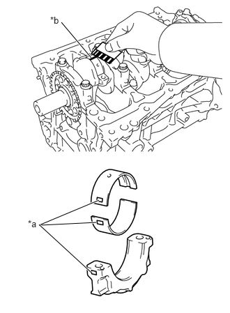
| *a | Number Mark |
| *b | Plastigage |
Measure the Plastigage at its widest point.
- Standard oil clearance:
0.019 to 0.053 mm (0.00075 to 0.00209 in.)
- Maximum oil clearance:
0.053 mm (0.00209 in.)
If the connecting rod oil clearance is greater than the maximum, replace the connecting rod bearings. If necessary, replace the crankshaft.
- NOTICE:
-
Completely remove the Plastigage after the measurement.
- HINT:
-
If replacing a connecting rod bearing, replace it with one that has the same number as its respective connecting rod cap. Each connecting rod bearing's standard thickness is indicated by mark 1, 2, or 3 on its surface.
- Standard Connecting Rod Large End Bore Diameter:
Mark Specified Condition 1 45.000 to 45.008 mm (1.77165 to 1.77196 in.) 2 45.009 to 45.016 mm (1.77201 to 1.77227 in.) 3 45.017 to 45.024 mm (1.77232 to 1.77259 in.)
- Standard Connecting Rod Bearing Thickness:
Mark Specified Condition 1 1.492 to 1.495 mm (0.05875 to 0.05885 in.) 2 1.496 to 1.498 mm (0.05890 to 0.05897 in.) 3 1.499 to 1.501 mm (0.05902 to 0.05909 in.)
- Standard Crankshaft Pin Diameter:
Mark Specified Condition 1, 2, 3 41.992 to 42.000 mm (1.65323 to 1.65354 in.)
9.INSPECT CONNECTING ROD BOLT
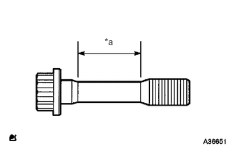
| *a | Measurement Area |
Using a vernier caliper, measure the diameter of the connecting rod bolt in the area shown in the illustration.
- Standard diameter:
6.6 to 6.7 mm (0.25985 to 0.26377 in.)
- Minimum diameter:
6.4 mm (0.25197 in.)
If the diameter is less than the minimum, replace the connecting rod bolt.
13411
10.INSPECT CRANKSHAFT
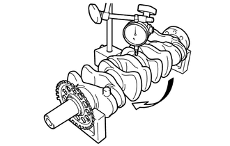
Using a dial indicator and V-blocks, measure the runout as shown in the illustration.
- Maximum runout:
0.03 mm (0.00118 in.)
If the runout is greater than the maximum, replace the crankshaft.
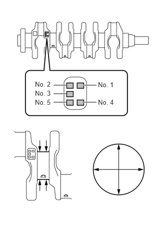
Using a micrometer, measure the diameter of each main journal.
- Standard diameter:
47.988 to 48.000 mm (1.88929 to 1.88976 in.)
If the diameter is not as specified, check the crankshaft oil clearance.
Check each main journal for taper and distortion as shown in the illustration.
- Maximum taper and out-of-round:
0.003 mm (0.00012 in.)
If the taper or out-of-round is greater than the maximum, replace the crankshaft.
- Standard Diameter (Reference):
Mark Specified Condition 0 47.999 to 48.000 mm (1.88973 to 1.88976 in.) 1 47.997 to 47.998 mm (1.88965 to 1.88968 in.) 2 47.995 to 47.996 mm (1.88957 to 1.88960 in.) 3 47.993 to 47.994 mm (1.88949 to 1.88952 in.) 4 47.991 to 47.992 mm (1.88941 to 1.88944 in.) 5 47.988 to 47.990 mm (1.88929 to 1.88936 in.)
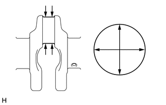
Using a micrometer, measure the diameter of each crank pin.
- Standard diameter:
41.992 to 42.000 mm (1.6532 to 1.6535 in.)
If the diameter is not as specified, check the connecting rod oil clearance.
Inspect each crank pin for taper and distortion as shown in the illustration.
- Maximum taper and out-of-round:
0.003 mm (0.00012 in.)
If the taper or out-of-round is greater than the maximum, replace the crankshaft.
11.INSPECT CRANKSHAFT THRUST CLEARANCE
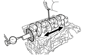
Using a dial indicator, measure the thrust clearance while prying the crankshaft back and forth with a screwdriver.
- Standard thrust clearance:
0.12 to 0.32 mm (0.0047 to 0.0126 in.)
- Maximum thrust clearance:
0.32 mm (0.0126 in.)
- HINT:
-
The thrust washer thickness is 1.89 to 1.94 mm (0.0744 to 0.0764 in.).
If the thrust clearance is greater than the maximum, replace the upper crankshaft thrust washers as a set. Check the crankshaft and cylinder block sub-assembly for wear. Repair or replace the parts if necessary.
12.INSPECT CRANKSHAFT OIL CLEARANCE
Check the crank journal and crankshaft bearing for pitting and scratches.
Install the crankshaft bearing.
Click hereEngine / Hybrid System>2NR-FE ENGINE MECHANICAL>CYLINDER BLOCK>REASSEMBLY
Place the crankshaft on the cylinder block sub-assembly.
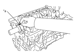
| *a | Plastigage |
Lay a strip of Plastigage across each journal.
Check the front marks and numbers, and install the crankshaft bearing caps on the cylinder block sub-assembly.
- HINT:
-
A number is marked on each crankshaft bearing cap to indicate the installation position.
Install the crankshaft bearing caps.
Click hereEngine / Hybrid System>2NR-FE ENGINE MECHANICAL>CYLINDER BLOCK>REASSEMBLY
- NOTICE:
-
Do not turn the crankshaft.
Remove the crankshaft bearing caps.
Click hereEngine / Hybrid System>2NR-FE ENGINE MECHANICAL>CYLINDER BLOCK>DISASSEMBLY
Measure the Plastigage at its widest point.
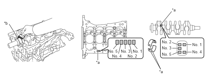
| *a | Number Mark | *b | Plastigage |
- Standard oil clearance:
0.014 to 0.038 mm (0.00055 to 0.00150 in.)
- Maximum oil clearance:
0.038 mm (0.00150 in.)
If the crankshaft oil clearance is greater than the maximum, replace the crankshaft bearing. If necessary, replace the crankshaft.
- NOTICE:
-
Remove the Plastigage completely after the measurement.
- HINT:
- ·
If replacing a crankshaft bearing, select a new one with the same number. If the number of the crankshaft bearing cannot be determined, calculate the correct crankshaft bearing number by adding together the numbers imprinted on the cylinder block sub-assembly and crankshaft. Then select a new crankshaft bearing with the calculated number according to the chart below. There are 4 sizes of standard bearings, marked "2", "3", "4" or "5" accordingly.
·EXAMPLE: Cylinder block "3" + Crankshaft "5" = Total number 8 (Use bearing "4")
Cylinder block + Crankshaft 0 to 2 3 to 5 6 to 8 9 to 11 Bearing to be used "2" "3" "4" "5"
- Standard Cylinder Block Journal Bore Diameter:
Mark Specified Condition 0 52.000 to 52.002 mm (2.04724 to 2.04731 in.) 1 52.003 to 52.004 mm (2.04736 to 2.04739 in.) 2 52.005 to 52.006 mm (2.04744 to 2.04747 in.) 3 52.007 to 52.009 mm (2.04752 to 2.04759 in.) 4 52.010 to 52.011 mm (2.04764 to 2.04767 in.) 5 52.012 to 52.013 mm (2.04772 to 2.04775 in.) 6 52.014 to 52.016 mm (2.04780 to 2.04786 in.)
- Standard Crankshaft Journal Diameter:
Mark Specified Condition 0 47.999 to 48.000 mm (1.88973 to 1.88976 in.) 1 47.997 to 47.998 mm (1.88965 to 1.88968 in.) 2 47.995 to 47.996 mm (1.88957 to 1.88960 in.) 3 47.993 to 47.994 mm (1.88949 to 1.88952 in.) 4 47.991 to 47.992 mm (1.88941 to 1.88944 in.) 5 47.988 to 47.990 mm (1.88929 to 1.88936 in.)
- Standard Bearing Center Wall Thickness:
Mark Specified Condition 2 1.994 to 1.997 mm (0.07851 to 0.07862 in.) 3 1.998 to 2.000 mm (0.07867 to 0.07874 in.) 4 2.001 to 2.003 mm (0.07878 to 0.07885 in.) 5 2.004 to 2.006 mm (0.07890 to 0.07897 in.)
11416
13.INSPECT CRANKSHAFT BEARING CAP SET BOLT
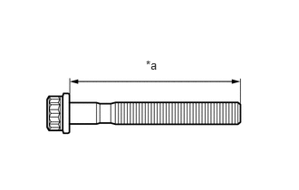
| *a | Measurement Length |
Using a vernier caliper, measure the length of the crankshaft bearing cap set bolt from the seat to the end.
- Standard length:
75.3 to 76.7 mm (2.9646 to 3.0196 in.)
- Maximum length:
77.2 mm (3.0394 in.)
If the length is greater than the maximum, replace the crankshaft bearing cap set bolt with a new one.
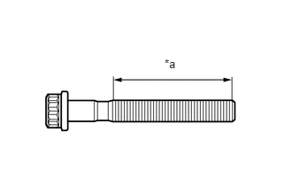
| *a | Measurement Area |
Using a vernier caliper, measure the diameter of the crankshaft bearing cap set bolt in the area shown in the illustration.
- Standard diameter:
9.94 to 9.96 mm (0.3914 to 0.3921 in.)
- Minimum diameter:
9.59 mm (0.3776 in.)
If the diameter is less than the minimum, replace the crankshaft bearing cap set bolt with a new one.
15708
14.INSPECT NO. 1 OIL NOZZLE SUB-ASSEMBLY
Check the No. 1 oil nozzle sub-assembly for damage or clogging.
- HINT:
-
If there is damage or clogging, replace the No. 1 oil nozzle sub-assembly.