POWER ASSIST SYSTEMS POWER STEERING SYSTEM C1544 Engine Revolution Signal Malfunction C1545 Engine Revolution Signal Malfunction C1573 Engine Revolution Signal Malfunction (Test Mode DTC)
DESCRIPTION
The ECM sends engine speed signals to the power steering ECU assembly.
| DTC No. | Detection Item | DTC Detection Condition | Trouble Area | Return-to-normal Condition | Note |
|---|---|---|---|---|---|
| C1544 | Engine Revolution Signal Malfunction | An engine speed signal error. | ·
Engine speed signal circuit ·
ECM ·
Power steering ECU assembly |
Ignition switch turned to ON again or after system confirmed to be normal | Power Steering Warning Light comes on. |
| C1545 | Engine Revolution Signal Malfunction | An engine speed signal error. | ·
Engine speed signal circuit ·
ECM ·
Power steering ECU assembly |
Ignition switch turned to ON again or after system confirmed to be normal | Power Steering Warning Light does not illuminate (normal reset). |
| C1573 | Engine Revolution Signal Malfunction (Test Mode DTC) | An engine speed signal error (Test Mode DTC). | ·
Engine speed signal circuit ·
ECM ·
Power steering ECU assembly |
- | Power Steering Warning Light does not illuminate (normal reset). |
WIRING DIAGRAM
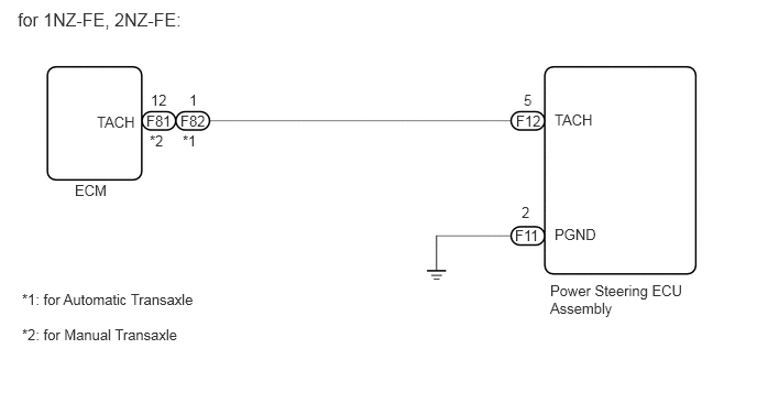
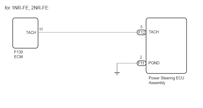
CAUTION / NOTICE / HINT
- NOTICE:
-
If the power steering ECU assembly, electric power steering column sub-assembly or power steering motor assembly have been replaced, perform torque sensor zero point calibration.
-
Click hereSteering>POWER ASSIST SYSTEMS>POWER STEERING SYSTEM>CALIBRATION
PROCEDURE
Perform the signal check in the Test Mode procedure.
- Chassis > EMPS > Utility
-
Tester Display Signal Check - 50005 13 3
- OK:
Test mode DTC C1573 is cleared.
- Result:
Proceed to OK NG
OK
Click hereGeneral>INTRODUCTION>HOW TO TROUBLESHOOT ECU CONTROLLED SYSTEMS>HOW TO PROCEED WITH TROUBLESHOOTING
NG
Check whether DTCs for the ECM are output.
- Powertrain > Engine and ECT > Trouble Codes
- 50001 234
- OK:
DTCs for ECM are not output.
- Result:
Result Proceed to OK A NG 1NZ-FE (for Automatic Transaxle) B 2NZ-FE (for Manual Transaxle) C 2NZ-FE (for Automatic Transaxle) D 1NR-FE E 2NR-FE F
A
B
C
D
E
F
Turn the ignition switch off.
Connect the GTS to the DLC3.
Turn the ignition switch to ON.
Turn the GTS on.
Enter the following menus: Chassis / EMPS / Data List.
Check the values indicated on the GTS and on the tachometer.
- Chassis > EMPS > Data List
-
Tester Display Measurement Item Range Normal Condition Diagnostic Note Engine Revolution Engine speed Min.: 0 rpm
Max.: 8160 rpmNo significant fluctuation. The engine is running at a constant speed.
- Chassis > EMPS > Data List
-
Tester Display Engine Revolution - 50003 13 8
- OK:
Abnormal change in engine speed does not occur when idling.
- Result:
Proceed to OK NG
OK
Click hereGeneral>INTRODUCTION>HOW TO TROUBLESHOOT ECU CONTROLLED SYSTEMS>HOW TO PROCEED WITH TROUBLESHOOTING
NG
for 1NZ-FE, 2NZ-FE
Disconnect the F12 power steering ECU assembly connector.
Disconnect the F81*1 or F82*2 ECM connector.
*1: for Manual Transaxle
*2: for Automatic Transaxle
Measure the resistance according to the value(s) in the table below.
- Standard Resistance:
for Manual Transaxle Tester Connection Condition Specified Condition F12-5 (TACH) - F81-12 (TACH) Always Below 1 Ω F12-5 (TACH) or F81-12 (TACH) - Body ground Always 10 kΩ or higher
for Automatic Transaxle Tester Connection Condition Specified Condition F12-5 (TACH) - F82-1 (TACH) Always Below 1 Ω F12-5 (TACH) or F82-1 (TACH) - Body ground Always 10 kΩ or higher
for 1NR-FE, 2NR-FE
Disconnect the F12 power steering ECU assembly connector.
Disconnect the F130 ECM connector.
Measure the resistance according to the value(s) in the table below.
- Standard Resistance:
Tester Connection Condition Specified Condition F12-5 (TACH) - F130-11 (TACH) Always Below 1 Ω F12-5 (TACH) or F130-11 (TACH) - Body ground Always 10 kΩ or higher
- Result:
Proceed to OK NG
OK
NG
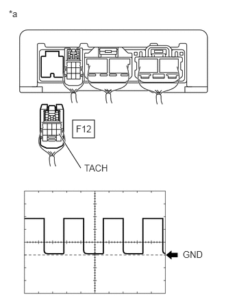
| *a | Rear view of wire harness connector
(to Power Steering ECU Assembly) |
Disconnect the power steering ECU assembly connector.
Start the engine.
Check the waveform of the power steering ECU assembly using an oscilloscope while idling the engine.
- OK:
Tester Connection Condition Specified Condition F12-5 (TACH) - Body ground Idling Correct waveform is as shown
| Item | Contents |
|---|---|
| Tool Setting | 5 V/DIV., 10 ms./DIV. |
- HINT:
-
The wavelength becomes shorter as the engine speed increases.
- Result:
Result Proceed to OK A NG 1NZ-FE (for Automatic Transaxle) B 2NZ-FE (for Manual Transaxle) C 2NZ-FE (for Automatic Transaxle) D 1NR-FE E 2NR-FE F
A
B
C
D
E
Click hereEngine / Hybrid System>1NR-FE ENGINE CONTROL>SFI SYSTEM>HOW TO PROCEED WITH TROUBLESHOOTING
F
Click hereEngine / Hybrid System>2NR-FE ENGINE CONTROL>SFI SYSTEM>HOW TO PROCEED WITH TROUBLESHOOTING