STEERING COLUMN STEERING COLUMN ASSEMBLY(for TMT Made) INSTALLATION
PROCEDURE

 45879A
1.INSTALL BREAK AWAY CAPSULE
Install 2 new break away capsules to the steering column assembly.
2.INSTALL STEERING COLUMN ASSEMBLY
Install the steering column assembly to the instrument panel reinforcement assembly with the bolt and 2 nuts.
- Torque:
- 25 N*m (255 kgf*cm, 18 ft.*lbf)
Engage the wire harness clamp to install the wire harness to the power steering ECU assembly.
Connect the 2 connectors to the power steering ECU assembly.
Connect all the connectors and engage the 2 clamps to install the wire harness to the steering column assembly.
45209
3.INSTALL STEERING SLIDING YOKE SUB-ASSEMBLY
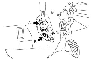
| *a | Matchmark |
Align the matchmarks on the steering sliding yoke sub-assembly and the steering link assembly.
Install the steering sliding yoke sub-assembly to the steering link assembly.
Install bolt B.
- Torque:
- 35.3 N*m (360 kgf*cm, 26 ft.*lbf)
Tighten bolt A.
- Torque:
- 35.3 N*m (360 kgf*cm, 26 ft.*lbf)
45259A
4.INSTALL COLUMN HOLE COVER SILENCER SHEET
Install the column hole cover silencer sheet with the 2 clips.
5.INSTALL COMBINATION SWITCH ASSEMBLY WITH SPIRAL CABLE SUB-ASSEMBLY
Using pliers, pinch the clamp and attach the claw to install the combination switch assembly with spiral cable sub-assembly to the steering column assembly.
Connect all the connectors to the combination switch assembly with spiral cable sub-assembly.
- NOTICE:
- ·
Do not replace the spiral cable with sensor sub-assembly with the battery connected and the ignition switch ON.
·Do not rotate the spiral cable with sensor sub-assembly without the steering wheel assembly with the battery connected and the ignition switch ON.
·When rotating the spiral cable with sensor sub-assembly to check the operation of the sub-assembly (checking for abnormal noise, checking the Data List, etc.), make sure to perform the inspection with the steering wheel assembly installed.
·Ensure that the steering wheel is installed and aligned straight when inspecting the steering sensor.
45286B
6.INSTALL UPPER STEERING COLUMN COVER
Engage the claw to install the upper steering column cover.
45287
7.INSTALL LOWER STEERING COLUMN COVER
Engage the 3 claws to install the lower steering column cover.
Install the 3 screws.
45289A
8.INSTALL STEERING COLUMN COVER SUPPORT (w/ Smart Entry and Start System)
Engage the 4 claws and install the steering column cover support.
9.PLACE FRONT WHEELS FACING STRAIGHT AHEAD
84306
10.ADJUST SPIRAL CABLE SUB-ASSEMBLY
55106
11.INSTALL BRAKE PEDAL SUPPORT SUB-ASSEMBLY (for LHD)
55106
12.INSTALL BRAKE PEDAL SUPPORT SUB-ASSEMBLY (for RHD)
45100
13.INSTALL STEERING WHEEL ASSEMBLY
45130
14.INSTALL HORN BUTTON ASSEMBLY
15. PERFORM CALIBRATION OF TORQUE SENSOR ZERO POINT