Home › Vehicle Exterior › WINDOW / GLASS › POWER WINDOW CONTROL SYSTEM › 2017.10–2018.01
RM30M0E _59 Vehicle Exterior _017121 WINDOW / GLASS _0086434 POWER WINDOW CONTROL SYSTEM J

WINDOW / GLASS  POWER WINDOW CONTROL SYSTEM  Driver Side Power Window does not Operate with Power Window Master Switch  


DESCRIPTION

When the engine is running or the ignition switch is ON, the front power window regulator motor assembly (driver side) is operated by the power window regulator master switch assembly. The front power window regulator motor assembly (driver side) has motor, regulator and ECU functions.

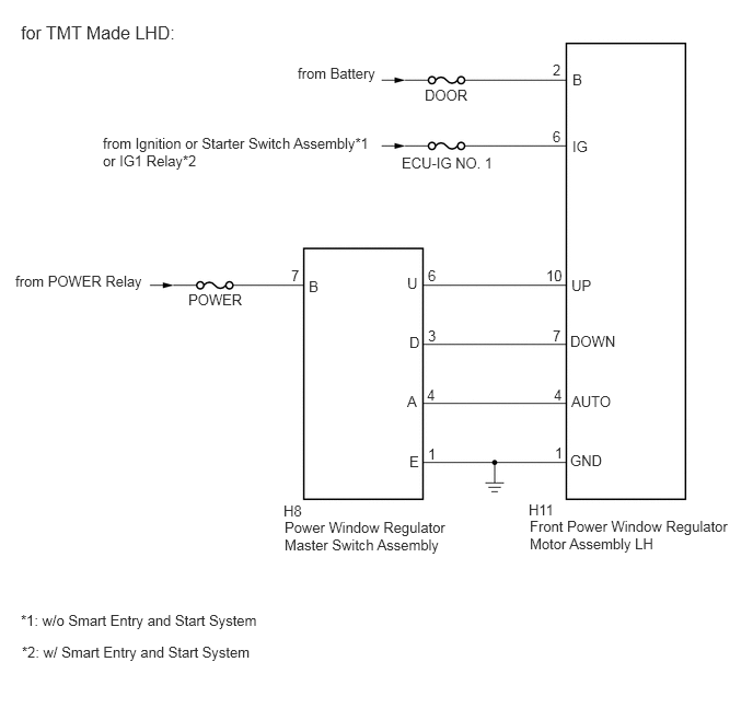
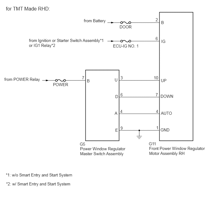
WIRING DIAGRAM
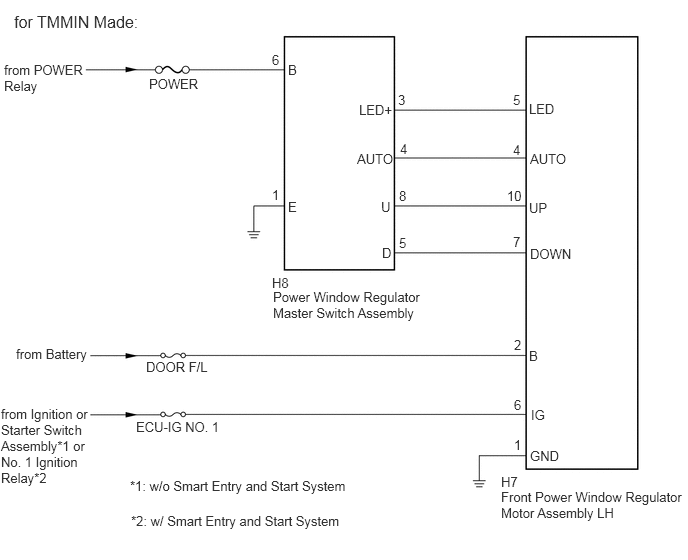
C296315E02
0.042,0.646 0.99,1 0.948,0.354 10 false from POWER Relay 1.552,0.792 2.146,0.99 0.594,0.198 10 false POWER 0.146,0.125 2.01,0.458 1.865,0.333 12 false for TMMIN Made: 0.167,3.604 0.958,3.781 0.792,0.177 10 false from Battery 0.01,4.229 0.906,5.156 0.896,0.927 10 false from Ignition or Starter Switch Assembly*1 or No. 1 Ignition Relay*2 1.354,4.979 3.833,5.208 2.479,0.229 10 false *1: w/o Smart Entry and Start System 1.365,5.344 3.844,5.573 2.479,0.229 10 false *2: w/ Smart Entry and Start System 1.417,4.365 2.354,4.563 0.938,0.198 10 false ECU-IG NO. 1 1.521,3.74 2.25,3.948 0.729,0.208 10 false DOOR F/L 5.219,4.938 5.448,5.146 0.229,0.208 10 false H7 5.219,5.094 7.156,5.552 1.938,0.458 10 false Front Power Window Regulator Motor Assembly LH 2.833,2.865 3.063,3.073 0.229,0.208 10 false H8 2.844,3.01 4.625,3.396 1.781,0.385 10 false Power Window Regulator Master Switch Assembly 5.521,4.667 5.844,4.844 0.323,0.177 10 false GND 5.531,4.24 5.74,4.417 0.208,0.177 10 false IG 5.51,3.625 5.719,3.802 0.208,0.177 10 false B 5.521,2.563 6.01,2.729 0.49,0.167 10 false DOWN 5.51,2.083 6,2.25 0.49,0.167 10 false UP 5.521,1.573 6.01,1.74 0.49,0.167 10 false AUTO 5.51,1.052 6,1.219 0.49,0.167 10 false LED 3.74,1.063 4.229,1.229 0.49,0.167 10 false LED+ 3.719,1.573 4.208,1.74 0.49,0.167 10 false AUTO 3.969,2.073 4.115,2.26 0.146,0.188 10 false U 3.979,2.552 4.177,2.729 0.198,0.177 10 false D 4.156,2.448 4.292,2.625 0.135,0.177 10 false 5 4.156,1.958 4.292,2.135 0.135,0.177 10 false 8 4.167,1.469 4.302,1.646 0.135,0.177 10 false 4 4.146,0.958 4.281,1.135 0.135,0.177 10 false 3 5.344,0.958 5.479,1.135 0.135,0.177 10 false 5 5.344,1.479 5.479,1.656 0.135,0.177 10 false 4 5.281,1.958 5.479,2.167 0.198,0.208 10 false 10 5.344,2.438 5.469,2.656 0.125,0.219 10 false 7 5.354,3.51 5.479,3.688 0.125,0.177 10 false 2 5.354,4.135 5.479,4.313 0.125,0.177 10 false 6 5.354,4.552 5.479,4.729 0.125,0.177 10 false 1 3,2.073 3.198,2.25 0.198,0.177 10 false E 2.833,1.948 2.958,2.125 0.125,0.177 10 false 1 3,0.646 3.208,0.823 0.208,0.177 10 false B 2.833,0.542 2.958,0.719 0.125,0.177 10 false 6

E367689E04
2.833,0.615 3.667,0.844 0.833,0.229 10 false from Battery 4.042,0.823 4.563,1.01 0.521,0.188 10 false DOOR 0.979,1.281 3.563,1.688 2.583,0.406 10 false from Ignition or Starter Switch Assembly*1 or IG1 Relay*2 3.823,1.469 4.792,1.667 0.969,0.198 10 false ECU-IG NO. 1 5.26,0.583 5.427,0.76 0.167,0.177 10 false 2 5.448,0.677 5.615,0.854 0.167,0.177 10 false B 5.26,1.219 5.427,1.396 0.167,0.177 10 false 6 5.448,1.313 5.688,1.49 0.24,0.177 10 false IG 0.146,2.594 1.469,2.792 1.323,0.198 10 false from POWER Relay 1.792,2.771 2.479,2.969 0.688,0.198 10 false POWER 2.771,2.542 2.938,2.719 0.167,0.177 10 false 7 2.938,2.646 3.104,2.823 0.167,0.177 10 false B 3.875,2.615 4.042,2.792 0.167,0.177 10 false U 4.073,2.542 4.24,2.719 0.167,0.177 10 false 6 3.896,3.177 4.063,3.354 0.167,0.177 10 false D 4.073,3.115 4.24,3.292 0.167,0.177 10 false 3 3.875,3.74 4.042,3.917 0.167,0.177 10 false A 4.063,3.677 4.229,3.854 0.167,0.177 10 false 4 3.896,4.313 4.063,4.49 0.167,0.177 10 false E 4.073,4.24 4.24,4.417 0.167,0.177 10 false 1 5.438,2.635 5.698,2.813 0.26,0.177 10 false UP 5.198,2.542 5.479,2.75 0.281,0.208 10 false 10 5.427,3.167 5.948,3.354 0.521,0.188 10 false DOWN 5.26,3.115 5.469,3.281 0.208,0.167 10 false 7 5.271,3.677 5.438,3.854 0.167,0.177 10 false 4 5.438,3.74 5.958,3.927 0.521,0.188 10 false AUTO 5.281,4.229 5.448,4.406 0.167,0.177 10 false 1 5.427,4.302 5.948,4.49 0.521,0.188 10 false GND 2.698,4.781 3,4.969 0.302,0.188 10 false H8 2.708,4.938 4.281,5.313 1.573,0.375 10 false Power Window Regulator Master Switch Assembly 5.031,4.771 5.333,4.958 0.302,0.188 10 false H11 5.042,4.927 6.958,5.302 1.917,0.375 10 false Front Power Window Regulator Motor Assembly LH 0.198,5.823 2.76,6.063 2.563,0.24 10 false *1: w/o Smart Entry and Start System 0.208,6.125 2.771,6.365 2.563,0.24 10 false *2: w/ Smart Entry and Start System 0.198,0.208 1.958,0.5 1.76,0.292 12 false for TMT Made LHD:

E367689E05
2.833,0.615 3.667,0.844 0.833,0.229 10 false from Battery 4.042,0.823 4.563,1.01 0.521,0.188 10 false DOOR 0.979,1.281 3.563,1.688 2.583,0.406 10 false from Ignition or Starter Switch Assembly*1 or IG1 Relay*2 3.823,1.469 4.792,1.667 0.969,0.198 10 false ECU-IG NO. 1 5.26,0.583 5.427,0.76 0.167,0.177 10 false 2 5.448,0.677 5.615,0.854 0.167,0.177 10 false B 5.26,1.219 5.427,1.396 0.167,0.177 10 false 6 5.448,1.313 5.688,1.49 0.24,0.177 10 false IG 0.146,2.594 1.469,2.792 1.323,0.198 10 false from POWER Relay 1.792,2.771 2.479,2.969 0.688,0.198 10 false POWER 2.771,2.542 2.938,2.719 0.167,0.177 10 false 7 2.938,2.646 3.104,2.823 0.167,0.177 10 false B 3.875,2.615 4.042,2.792 0.167,0.177 10 false U 4.073,2.542 4.24,2.719 0.167,0.177 10 false 3 3.896,3.177 4.063,3.354 0.167,0.177 10 false D 4.073,3.115 4.24,3.292 0.167,0.177 10 false 6 3.875,3.74 4.042,3.917 0.167,0.177 10 false A 4.063,3.677 4.229,3.854 0.167,0.177 10 false 4 3.896,4.313 4.063,4.49 0.167,0.177 10 false E 4.073,4.24 4.24,4.417 0.167,0.177 10 false 9 5.438,2.635 5.698,2.813 0.26,0.177 10 false UP 5.198,2.542 5.479,2.75 0.281,0.208 10 false 10 5.427,3.167 5.948,3.354 0.521,0.188 10 false DOWN 5.26,3.115 5.469,3.281 0.208,0.167 10 false 7 5.271,3.677 5.438,3.854 0.167,0.177 10 false 4 5.438,3.74 5.958,3.927 0.521,0.188 10 false AUTO 5.281,4.229 5.448,4.406 0.167,0.177 10 false 1 5.427,4.302 5.948,4.49 0.521,0.188 10 false GND 2.698,4.781 3,4.969 0.302,0.188 10 false G5 2.708,4.938 4.281,5.313 1.573,0.375 10 false Power Window Regulator Master Switch Assembly 5.031,4.771 5.417,4.99 0.385,0.219 10 false G11 5.042,4.927 6.958,5.302 1.917,0.375 10 false Front Power Window Regulator Motor Assembly RH 0.198,5.823 2.76,6.063 2.563,0.24 10 false *1: w/o Smart Entry and Start System 0.208,6.125 2.771,6.365 2.563,0.24 10 false *2: w/ Smart Entry and Start System 0.198,0.188 2.292,0.5 2.094,0.313 12 false for TMT Made RHD:

CAUTION / NOTICE / HINT

NOTICE:

Inspect the fuses for circuits related to this system before performing the following inspection procedure.


HINT:
·

When the front power window regulator motor assembly (driver side) is reinstalled or replaced, the power window control system must be initialized.


·

Replacing the door glass or door glass run may cause a difference to exist between the current door glass position and the position memorized in the ECU. In this case, the jam protection function may work improperly. Return the system to the pre-initialized condition and reinitialize the system.

1.

Disconnect the power window regulator motor connector during power window operation. This will return the motor to the pre-initialized condition.

HINT:

The auto up function will not work unless initialization is completed.


·

Inspect the fuses for circuits related to this system before performing the following inspection procedure.


PROCEDURE

1.CHECK VEHICLE TYPE
a.

Check vehicle type.


Result:
Result Proceed to
for TMMIN Made A
for TMT Made B


A

2.INSPECT POWER WINDOW REGULATOR MASTER SWITCH ASSEMBLY

B

6.INSPECT POWER WINDOW REGULATOR MASTER SWITCH ASSEMBLY
2.INSPECT POWER WINDOW REGULATOR MASTER SWITCH ASSEMBLY
a.

Remove the power window regulator master switch assembly.

Click hereVehicle Exterior>WINDOW / GLASS>POWER WINDOW MASTER SWITCH(for TMMIN Made)>REMOVAL


b.

Inspect the power window regulator master switch assembly.

Click hereVehicle Exterior>WINDOW / GLASS>POWER WINDOW MASTER SWITCH(for TMMIN Made)>INSPECTION


Result:
Proceed to
OK
NG


OK

3.CHECK HARNESS AND CONNECTOR (POWER WINDOW REGULATOR MASTER SWITCH ASSEMBLY - POWER SOURCE)

NG

REPLACE POWER WINDOW REGULATOR MASTER SWITCH ASSEMBLY

3.CHECK HARNESS AND CONNECTOR (POWER WINDOW REGULATOR MASTER SWITCH ASSEMBLY - POWER SOURCE)
a.
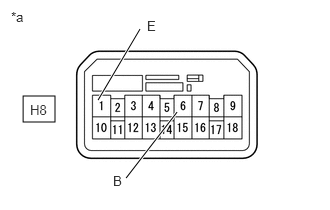
B276330C53
0.24,1 0.573,1.271 0.333,0.271 1.844,1.167 1.313,1.854 true 1.021,1.042 1.458,0.302 true 1.177,1.802 1.438,2.083 0.26,0.281 10 false B 1.531,0.188 1.688,0.385 0.156,0.198 10 false E 0.115,0.094 0.427,0.292 0.313,0.198 10 false *a 0.313,1.063 0.625,1.26 0.313,0.198 10 false H8
*a Front view of wire harness connector
(to Power Window Regulator Master Switch Assembly)


Disconnect the power window regulator master switch assembly connector.


b.

Measure the voltage according to the value(s) in the table below.

Standard Voltage:
Tester Connection Switch Condition Specified Condition
H8-6 (B) - Body ground Ignition switch ON 11 to 14 V


c.

Measure the resistance according to the value(s) in the table below.

Standard Resistance:
Tester Connection Condition Specified Condition
H8-1 (E) - Body ground Always Below 1 Ω


Result:
Proceed to
OK
NG


OK

4.CHECK HARNESS AND CONNECTOR (FRONT POWER WINDOW REGULATOR MOTOR ASSEMBLY LH - POWER SOURCE)

NG

REPAIR OR REPLACE HARNESS AND CONNECTOR

4.CHECK HARNESS AND CONNECTOR (FRONT POWER WINDOW REGULATOR MOTOR ASSEMBLY LH - POWER SOURCE)
a.
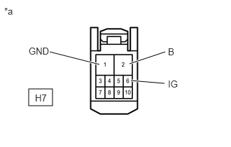
B210256C06
0.427,1.323 0.781,1.573 0.354,0.25 0.74,0.771 1.479,0.958 true 1.927,0.948 2.458,0.771 true 1.948,1.198 2.448,1.24 true 0.427,0.677 0.76,0.854 0.333,0.177 10 false GND 2.5,0.688 2.656,0.885 0.156,0.198 10 false B 0.063,0.083 0.375,0.281 0.313,0.198 10 false *a 2.5,1.167 2.75,1.365 0.25,0.198 10 false IG 0.521,1.375 0.771,1.573 0.25,0.198 10 false H7
*a Front view of wire harness connector
(to Front Power Window Regulator Motor Assembly LH)


Disconnect the front power window regulator motor assembly LH connector.


b.

Measure the voltage according to the value(s) in the table below.

Standard Voltage:
Tester Connection Switch Condition Specified Condition
H7-2 (B) - Body ground Always 11 to 14 V
H7-6 (IG) - Body ground Ignition switch ON 11 to 14 V


c.

Measure the resistance according to the value(s) in the table below.

Standard Resistance:
Tester Connection Condition Specified Condition
H7-1 (GND) - Body ground Always Below 1Ω


Result:
Proceed to
OK
NG


OK

5.CHECK HARNESS AND CONNECTOR (POWER WINDOW REGULATOR MASTER SWITCH ASSEMBLY - FRONT POWER WINDOW REGULATOR MOTOR ASSEMBLY LH)

NG

REPAIR OR REPLACE HARNESS AND CONNECTOR

5.CHECK HARNESS AND CONNECTOR (POWER WINDOW REGULATOR MASTER SWITCH ASSEMBLY - FRONT POWER WINDOW REGULATOR MOTOR ASSEMBLY LH)
a.

Disconnect the H8 power window regulator master switch assembly connector.


b.

Disconnect the H7 front power window regulator motor assembly LH connector.


c.

Measure the resistance according to the value(s) in the table below.

Standard Resistance:
Tester Connection Condition Specified Condition
H8-8 (U) - H7-10 (UP) Always Below 1Ω
H8-5 (D) - H7-7 (DOWN) Always Below 1Ω
H8-4 (AUTO) - H7-4 (AUTO) Always Below 1Ω
H8-3 (LED+) - H7-5 (LED) Always Below 1Ω
H8-8 (U) or H7-10 (UP) - Body ground Always 10 kΩ or higher
H8-5 (D) or H7-7 (DOWN) - Body ground Always 10 kΩ or higher
H8-4 (AUTO) or H7-4 (AUTO) - Body ground Always 10 kΩ or higher
H8-3 (LED+) or H7-5 (LED) - Body ground Always 10 kΩ or higher


Result:
Proceed to
OK
NG


OK

REPLACE POWER WINDOW REGULATOR MOTOR ASSEMBLY LH OR RH

NG

REPAIR OR REPLACE HARNESS OR CONNECTOR

6.INSPECT POWER WINDOW REGULATOR MASTER SWITCH ASSEMBLY
a.

Remove the power window regulator master switch assembly.

Click hereVehicle Exterior>WINDOW / GLASS>POWER WINDOW MASTER SWITCH(for TMT Made)>REMOVAL


b.

Inspect the power window regulator master switch assembly.

Click hereVehicle Exterior>WINDOW / GLASS>POWER WINDOW MASTER SWITCH(for TMT Made)>INSPECTION


Result:
Proceed to
OK
NG


OK

7.CHECK HARNESS AND CONNECTOR (POWER WINDOW REGULATOR MASTER SWITCH ASSEMBLY - POWER SOURCE)

NG

REPLACE POWER WINDOW REGULATOR MASTER SWITCH ASSEMBLY

7.CHECK HARNESS AND CONNECTOR (POWER WINDOW REGULATOR MASTER SWITCH ASSEMBLY - POWER SOURCE)
a.

for LHD

i.
B276330C67
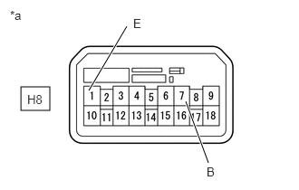
0.24,1 0.573,1.271 0.333,0.271 2.135,1.167 2.396,1.875 true 1.021,1.042 1.458,0.302 true 2.375,1.896 2.573,2.125 0.198,0.229 10 false B 1.531,0.188 1.688,0.385 0.156,0.198 10 false E 0.115,0.094 0.427,0.292 0.313,0.198 10 false *a 0.313,1.063 0.625,1.26 0.313,0.198 10 false H8
*a Front view of wire harness connector
(to Power Window Regulator Master Switch Assembly)


Disconnect the power window regulator master switch assembly connector.


ii.

Measure the voltage according to the value(s) in the table below.

Standard Voltage:
Tester Connection Switch Condition Specified Condition
H8-7 (B) - Body ground Ignition switch ON 11 to 14 V


iii.

Measure the resistance according to the value(s) in the table below.

Standard Resistance:
Tester Connection Condition Specified Condition
H8-1 (E) - Body ground Always Below 1 Ω


b.

for RHD

i.
B276330C65
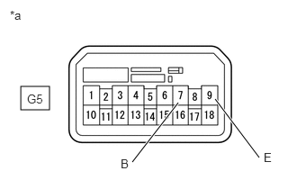
0.24,1 0.573,1.271 0.333,0.271 2.063,1.188 1.531,1.875 true 2.49,1.146 3,1.823 true 1.396,1.813 1.656,2.094 0.26,0.281 10 false B 3.052,1.74 3.208,1.938 0.156,0.198 10 false E 0.115,0.094 0.427,0.292 0.313,0.198 10 false *a 0.313,1.063 0.625,1.26 0.313,0.198 10 false G5
*a Front view of wire harness connector
(to Power Window Regulator Master Switch Assembly)


Disconnect the power window regulator master switch assembly connector.


ii.

Measure the voltage according to the value(s) in the table below.

Standard Voltage:
Tester Connection Switch Condition Specified Condition
G5-7 (B) - Body ground Ignition switch ON 11 to 14 V


iii.

Measure the resistance according to the value(s) in the table below.

Standard Resistance:
Tester Connection Condition Specified Condition
G5-9 (E) - Body ground Always Below 1 Ω


Result:
Proceed to
OK
NG


OK

8.CHECK HARNESS AND CONNECTOR (FRONT POWER WINDOW REGULATOR MOTOR ASSEMBLY LH OR RH - POWER SOURCE)

NG

REPAIR OR REPLACE HARNESS AND CONNECTOR

8.CHECK HARNESS AND CONNECTOR (FRONT POWER WINDOW REGULATOR MOTOR ASSEMBLY LH OR RH - POWER SOURCE)
a.

for LHD

i.
B210256C15
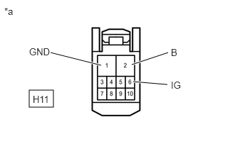
0.427,1.323 0.781,1.573 0.354,0.25 0.74,0.771 1.479,0.958 true 1.927,0.948 2.458,0.771 true 1.948,1.198 2.448,1.24 true 0.427,0.677 0.76,0.854 0.333,0.177 10 false GND 2.5,0.688 2.656,0.885 0.156,0.198 10 false B 0.063,0.083 0.375,0.281 0.313,0.198 10 false *a 2.5,1.167 2.75,1.365 0.25,0.198 10 false IG 0.479,1.375 0.771,1.615 0.292,0.24 10 false H11
*a Front view of wire harness connector
(to Front Power Window Regulator Motor Assembly LH)


Disconnect the front power window regulator motor assembly LH connector.


ii.

Measure the voltage according to the value(s) in the table below.

Standard Voltage:
Tester Connection Switch Condition Specified Condition
H11-2 (B) - Body ground Always 11 to 14 V
H11-6 (IG) - Body ground Ignition switch ON 11 to 14 V


iii.

Measure the resistance according to the value(s) in the table below.

Standard Resistance:
Tester Connection Condition Specified Condition
H11-1 (GND) - Body ground Always Below 1Ω


iv.

Reconnect the front power window regulator motor assembly LH connector.


b.

for RHD

i.
B210256C16
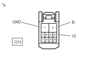
0.427,1.323 0.781,1.573 0.354,0.25 0.74,0.771 1.479,0.958 true 1.927,0.948 2.458,0.771 true 1.948,1.198 2.448,1.24 true 0.427,0.677 0.76,0.854 0.333,0.177 10 false GND 2.5,0.688 2.656,0.885 0.156,0.198 10 false B 0.063,0.083 0.375,0.281 0.313,0.198 10 false *a 2.5,1.167 2.75,1.365 0.25,0.198 10 false IG 0.5,1.375 0.813,1.583 0.313,0.208 10 false G11
*a Front view of wire harness connector
(to Front Power Window Regulator Motor Assembly RH)


Disconnect the front power window regulator motor assembly RH connector.


ii.

Measure the voltage according to the value(s) in the table below.

Standard Voltage:
Tester Connection Switch Condition Specified Condition
G11-2 (B) - Body ground Always 11 to 14 V
G11-6 (IG) - Body ground Ignition switch ON 11 to 14 V


iii.

Measure the resistance according to the value(s) in the table below.

Standard Resistance:
Tester Connection Condition Specified Condition
G11-1 (GND) - Body ground Always Below 1Ω


iv.

Reconnect the front power window regulator motor assembly RH connector.


Result:
Proceed to
OK
NG


OK

9.CHECK HARNESS AND CONNECTOR (POWER WINDOW REGULATOR MASTER SWITCH ASSEMBLY - FRONT POWER WINDOW REGULATOR MOTOR ASSEMBLY LH OR RH)

NG

REPAIR OR REPLACE HARNESS AND CONNECTOR

9.CHECK HARNESS AND CONNECTOR (POWER WINDOW REGULATOR MASTER SWITCH ASSEMBLY - FRONT POWER WINDOW REGULATOR MOTOR ASSEMBLY LH OR RH)
a.

for LHD

i.

Disconnect the H8 power window regulator master switch assembly connector.


ii.

Disconnect the H11 front power window regulator motor assembly LH connector.


iii.

Measure the resistance according to the value(s) in the table below.

Standard Resistance:
Tester Connection Condition Specified Condition
H8-6 (U) - H11-10 (UP) Always Below 1Ω
H8-3 (D) - H11-7 (DOWN) Always Below 1Ω
H8-4 (A) - H11-4 (AUTO) Always Below 1Ω
H8-6 (U) or H11-10 (UP) - Body ground Always 10 kΩ or higher
H8-3 (D) or H11-7 (DOWN) - Body ground Always 10 kΩ or higher
H8-4 (A) or H11-4 (AUTO) - Body ground Always 10 kΩ or higher


iv.

Reconnect the H8 power window regulator master switch assembly connector.


v.

Reconnect the H11 front power window regulator motor assembly LH connector.


b.

for RHD

i.

Disconnect the G5 power window regulator master switch assembly connector.


ii.

Disconnect the G11 front power window regulator motor assembly RH connector.


iii.

Measure the resistance according to the value(s) in the table below.

Standard Resistance:
Tester Connection Condition Specified Condition
G5-3 (U) - G11-10 (UP) Always Below 1Ω
G5-6 (D) - G11-7 (DOWN) Always Below 1Ω
G5-4 (A) - G11-4 (AUTO) Always Below 1Ω
G5-3 (U) or G11-10 (UP) - Body ground Always 10 kΩ or higher
G5-6 (D) or G11-7 (DOWN) - Body ground Always 10 kΩ or higher
G5-4 (A) or G11-4 (AUTO) - Body ground Always 10 kΩ or higher


iv.

Reconnect the G5 power window regulator master switch assembly connector.


v.

Reconnect the G11 front power window regulator motor assembly RH connector.


Result:
Proceed to
OK
NG


OK

REPLACE POWER WINDOW REGULATOR MOTOR ASSEMBLY LH OR RH

NG

REPAIR OR REPLACE HARNESS OR CONNECTOR