SUPPLEMENTAL RESTRAINT SYSTEMS SPIRAL CABLE(for TMMIN Made) INSTALLATION
CAUTION / NOTICE / HINT
- CAUTION:
-
Some of these service operations affect the SRS airbag system. Read the precautionary notices concerning the SRS airbag system before servicing.
-
Click hereVehicle Interior>SUPPLEMENTAL RESTRAINT SYSTEMS>AIRBAG SYSTEM>PRECAUTION
PROCEDURE

 1.INSPECT SPIRAL CABLE SUB-ASSEMBLY
- NOTICE:
-
If the spiral cable sub-assembly is installed with the center position misaligned, steering angle sensor value abnormal DTCs will be stored, and recovery will be impossible. In this case, replace the spiral cable sub-assembly with a new one.
Check the spiral cable sub-assembly center position.
- Standard:
Connector is at the highest point.
Alignment marks are aligned.
Colored roller or top of flat cable U-turn portion can be seen through the check window.
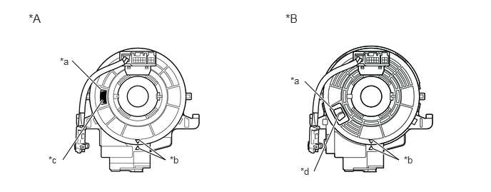
| *A | Colored Roller Visible Type | *B | Flat Cable Visible Type |
| *a | Check Window | *b | Alignment Marks |
| *c | Colored Roller | *d | Top of U-turn Portion of Flat Cable |
If the spiral cable sub-assembly is not at the center position, perform centering of the spiral cable sub-assembly.
- NOTICE:
-
Failure to observe the following precautions could result in breakage of the spiral cable sub-assembly.
- ·
Do not hold the airbag connector or wiring when rotating the spiral cable sub-assembly.
·Do not rotate with excessive force.
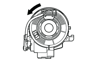

|
Rotation Direction |
Making sure to rotate in the counterclockwise direction only, slowly rotate the spiral cable sub-assembly in the counterclockwise direction until it stops.
- NOTICE:
-
Make sure to rotate in the counterclockwise direction only. Rotating in the clockwise direction can break the spiral cable sub-assembly or make centering impossible.
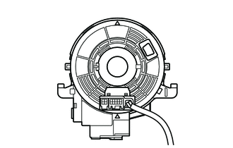
When the rotation stops, if the connector has passed the lowermost position, return the connector to the lowermost position as shown in the illustration.
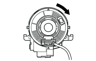
|
|
Rotation Direction |
Rotate the spiral cable sub-assembly back in the clockwise direction for approximately 2.5 turns so that the connector moves from the lowermost position to the topmost position.
- NOTICE:
-
With the connector in the lowermost position, rotating clockwise 5 turns or more could break the spiral cable sub-assembly.
Check that the spiral cable sub-assembly is centered.
- Standard:
Connector is at the highest point.
Alignment marks are aligned.
Colored roller or top of flat cable U-turn portion can be seen through the check window.
| *A | Colored Roller Visible Type | *B | Flat Cable Visible Type |
| *a | Check Window | *b | Alignment Marks |
| *c | Colored Roller | *d | Top of U-turn Portion of Flat Cable |
- NOTICE:
-
If centering cannot be achieved, the spiral cable sub-assembly may be broken, so replace it with a new one.
84306
2.INSTALL SPIRAL CABLE SUB-ASSEMBLY
Check that the ignition switch is off.
Check that the cable is disconnected from the negative (-) battery terminal.
- CAUTION:
-
Wait at least 90 seconds after disconnecting the cable from the negative (-) battery terminal to disable the SRS system.
Check that the front wheels are facing straight ahead.
Set the turn signal switch to the neutral position.
- NOTICE:
-
If it is not in the neutral position, the turn signal switch pin may snap.
Engage the 3 claws to install the spiral cable sub-assembly.
- NOTICE:
-
Pull the lock pin out before installing the steering wheel assembly when replacing the spiral cable sub-assembly with a new one.
Connect the connectors to the spiral cable sub-assembly.
45286B
3.INSTALL UPPER STEERING COLUMN COVER
45287
4.INSTALL LOWER STEERING COLUMN COVER
84306
5.ADJUST SPIRAL CABLE SUB-ASSEMBLY
- NOTICE:
-
Do not adjust the spiral cable sub-assembly with the battery connected and the ignition switch to ON.
Check that the ignition switch is off.
Check that the cable is disconnected from the negative (-) battery terminal.
- CAUTION:
-
Wait at least 90 seconds after disconnecting the cable from the negative (-) battery terminal to disable the SRS system.
Check the spiral cable sub-assembly center position.
- Standard:
Connector is at the highest point.
Colored roller or top of flat cable U-turn portion can be seen through the check window.
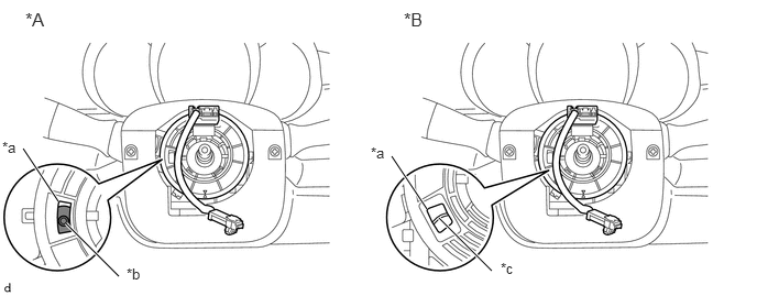
| *A | Colored Roller Visible Type | *B | Flat Cable Visible Type |
| *a | Check Window | *b | Colored Roller |
| *c | Top of U-turn Portion of Flat Cable | - | - |
If the spiral cable sub-assembly is not at the center position, perform centering of the spiral cable sub-assembly.
- NOTICE:
-
Failure to observe the following precautions could result in breakage of the spiral cable sub-assembly.
- ·
Do not rotate the spiral cable sub-assembly while the negative (-) battery cable is connected and the ignition switch is turned to ON.
·Do not hold the airbag connector or wiring when rotating the spiral cable sub-assembly.
·Do not rotate with excessive force.
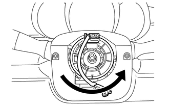
|
|
Rotation Direction |
Making sure to rotate in the counterclockwise direction only, slowly rotate the spiral cable sub-assembly in the counterclockwise direction until it stops.
- NOTICE:
-
Make sure to rotate in the counterclockwise direction only. Rotating in the clockwise direction can break the spiral cable sub-assembly or make centering impossible.
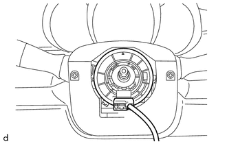
When the rotation stops, if the connector has passed the lowermost position, return the connector to the lowermost position as shown in the illustration.
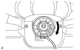
|
|
Rotation Direction |
Rotate the spiral cable sub-assembly back in the clockwise direction for approximately 2.5 turns so that the connector moves from the lowermost position to the topmost position.
- NOTICE:
-
With the connector in the lowermost position, rotating clockwise 5 turns or more could break the spiral cable sub-assembly.
Check that the spiral cable sub-assembly is centered.
- Standard:
Connector is at the highest point.
Colored roller or top of flat cable U-turn portion can be seen through the check window.
| *A | Colored Roller Visible Type | *B | Flat Cable Visible Type |
| *a | Check Window | *b | Colored Roller |
| *c | Top of U-turn Portion of Flat Cable | - | - |
- NOTICE:
-
If centering cannot be achieved, the spiral cable sub-assembly may be broken, so replace it with a new one.
45100
6.INSTALL STEERING WHEEL ASSEMBLY
7.CONNECT CABLE TO NEGATIVE BATTERY TERMINAL
- Torque:
- 5.4 N*m (55 kgf*cm, 48 in.*lbf)
- NOTICE:
-
When disconnecting the cable, some systems need to be initialized after the cable is reconnected.
-
Click hereGeneral>INTRODUCTION>REPAIR INSTRUCTION>INITIALIZATION
8.INSPECT SRS WARNING LIGHT