THEFT DETERRENT / KEYLESS ENTRY THEFT DETERRENT SYSTEM Security Indicator Light does not Operate Correctly
DESCRIPTION
- w/ Smart Entry and Start System:
-
When the theft deterrent system is in the arming preparation state, the body computer uses the communication line to send an illumination request to the certification ECU (smart key ECU assembly), and the certification ECU (smart key ECU assembly) illuminates the security indicator light.
-
When the theft deterrent system changes from the arming preparation state to armed state, the security indicator light changes from illuminated to flashing.
- w/o Smart Entry and Start System:
-
When the theft deterrent system is in the arming preparation state, the body computer illuminates the security indicator light.
-
When the theft deterrent system changes from the arming preparation state to armed state, the security indicator light changes from illuminated to flashing.
WIRING DIAGRAM
w/ Smart Entry and Start System
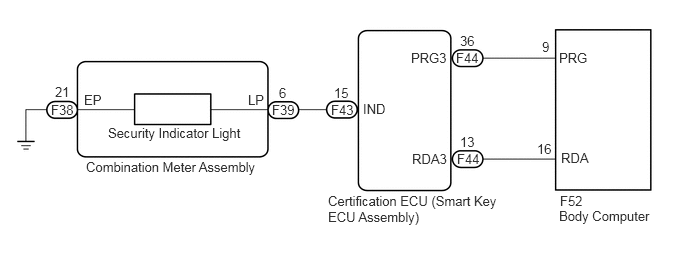
w/o Smart Entry and Start System
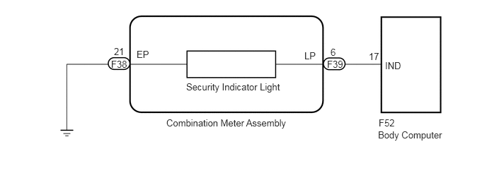
CAUTION / NOTICE / HINT
- NOTICE:
- ·
When replacing the combination meter assembly, always replace it with a new one. If a combination meter assembly which was installed to another vehicle is used, the information stored in it will not match the information from the vehicle and a DTC may be stored.
·As the security indicator light is shared with the immobiliser system, even if the theft deterrent system is canceled, the security indicator light will blink if the immobiliser system is set.*1
*1: w/ Smart Entry and Start System
PROCEDURE
Check the vehicle specification.
- Result:
Result Proceed to w/ Smart Entry and Start System A w/o Smart Entry and Start System B
A
B
Disconnect the F52 body computer connector.
Disconnect the F44 certification ECU (smart key ECU assembly) connector.
Measure the resistance according to the value(s) in the table below.
- Standard Resistance:
Tester Connection Condition Specified Condition F52-9 (PRG) - F44-36 (PRG3) Always Below 1 Ω F52-16 (RDA) - F44-13 (RDA3) Always Below 1 Ω F52-9 (PRG) or F44-36 (PRG3) - Body ground Always 10 kΩ or higher F52-16 (RDA) or F44-13 (RDA3) - Body ground Always 10 kΩ or higher
- Result:
Proceed to OK NG
OK
NG
Replace the body computer with a new or known good one.
Click herePower Source / Network>POWER DISTRIBUTION>MAIN BODY ECU>REMOVAL
- Result:
Proceed to NEXT
NEXT
Close all doors, and the engine hood.
Lock the doors using wireless operation.
Check that the security indicator light illuminates.
After 30 seconds have elapsed, check that the security indicator light changes from illuminated to flashing.
- Result:
Proceed to OK NG
OK
NG
Disconnect the F38 and F39 combination meter assembly connectors.
Disconnect the F52 body computer connector.
Measure the resistance according to the value(s) in the table below.
- Standard Resistance:
Tester Connection Condition Specified Condition F39-6 (LP) - F52-17 (IND) Always Below 1 Ω F39-6 (LP) - Body ground Always 10 kΩ or higher F52-17 (IND) - Body ground Always 10 kΩ or higher F38-21 (EP) - Body ground Always Below 1 Ω
- Result:
Proceed to OK NG
OK
NG
Replace the body computer with a new or known good one.
Click herePower Source / Network>POWER DISTRIBUTION>MAIN BODY ECU>REMOVAL
- Result:
Proceed to NEXT
NEXT
Close all doors, and the engine hood.
Lock the doors using wireless operation.
Check that the security indicator light illuminates.
After 30 seconds have elapsed, check that the security indicator light changes from illuminated to flashing.
- Result:
Proceed to OK NG
OK
NG