Home › Vehicle Interior › DOOR LOCK › POWER DOOR LOCK CONTROL SYSTEM › from 2018.01
RM30M0E _58 Vehicle Interior _017110 DOOR LOCK _0091388 POWER DOOR LOCK CONTROL SYSTEM J

DOOR LOCK  POWER DOOR LOCK CONTROL SYSTEM  All Doors LOCK/UNLOCK Functions do not Operate Via Door Control Switch or Door Key Cylinder  


DESCRIPTION

The body computer receives switch signals from the power window regulator master switch assembly and driver door key cylinder lock or unlock switch signals from the front door lock assembly LH*1 or RH*2. The body computer activates the door lock motor on each door according to these signals.

*1: for LHD

*2: for RHD


WIRING DIAGRAM
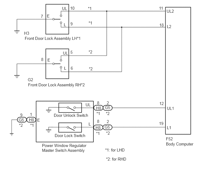
E391658E01
0.833,1.063 1.146,1.26 0.313,0.198 10 false H3 0.854,1.24 5.292,1.438 4.438,0.198 10 false Front Door Lock Assembly LH*1 1.615,0.469 1.771,0.667 0.156,0.198 10 false E 2.135,0.208 2.448,0.406 0.313,0.198 10 false UL 2.198,0.771 2.51,0.969 0.313,0.198 10 false L 1.406,0.479 1.688,0.719 0.281,0.24 10 false 7 2.417,0.198 2.698,0.438 0.281,0.24 10 false 10 2.427,0.74 2.708,0.979 0.281,0.24 10 false 9 3.052,1.708 3.365,1.906 0.313,0.198 10 false *2 3.031,0.208 3.417,0.458 0.385,0.25 10 false *1 3.052,0.708 3.365,0.906 0.313,0.198 10 false *1 3.063,2.292 3.375,2.49 0.313,0.198 10 false *2 2.167,1.75 2.479,1.948 0.313,0.198 10 false UL 2.208,2.271 2.521,2.469 0.313,0.198 10 false L 1.635,1.99 1.792,2.188 0.156,0.198 10 false E 1.417,1.969 1.698,2.208 0.281,0.24 10 false 8 2.438,2.271 2.719,2.51 0.281,0.24 10 false 6 2.427,1.719 2.708,1.958 0.281,0.24 10 false 5 0.958,2.667 1.271,2.865 0.313,0.198 10 false G2 0.969,2.844 5.406,3.042 4.438,0.198 10 false Front Door Lock Assembly RH*2 5.74,0.302 6.198,0.5 0.458,0.198 10 false UL2 5.75,0.833 6.208,1.031 0.458,0.198 10 false L2 5.479,0.198 5.792,0.396 0.313,0.198 10 false 11 5.49,0.781 5.802,0.979 0.313,0.198 10 false 18 5.75,3.656 6.208,3.854 0.458,0.198 10 false UL1 5.75,4.323 6.208,4.521 0.458,0.198 10 false L1 5.49,3.49 5.802,3.688 0.313,0.198 10 false 12 5.479,4.177 5.792,4.375 0.313,0.198 10 false 19 5.719,4.885 7.125,5.115 1.406,0.229 10 false Body Computer 5.719,4.708 6.177,4.906 0.458,0.198 10 false F52 3.615,3.625 3.927,3.823 0.313,0.198 10 false G5 3.604,4.302 3.917,4.5 0.313,0.198 10 false G5 0.646,4.052 0.958,4.25 0.313,0.198 10 false G5 1,4.052 1.313,4.25 0.313,0.198 10 false H8 3.313,3.646 3.625,3.844 0.313,0.198 10 false H8 3.292,4.323 3.604,4.521 0.313,0.198 10 false H8 1.448,4.938 3.063,5.771 1.615,0.833 10 false Power Window Regulator Master Switch Assembly 2.948,3.531 3.26,3.729 0.313,0.198 10 false UL 3.052,4.198 3.365,4.396 0.313,0.198 10 false L 1.281,4.063 1.438,4.26 0.156,0.198 10 false E 3.677,3.469 3.833,3.667 0.156,0.198 10 false 2 3.677,4.115 3.833,4.313 0.156,0.198 10 false 2 3.344,3.469 3.625,3.708 0.281,0.24 10 false 8 3.344,4.104 3.625,4.344 0.281,0.24 10 false 8 3.323,3.833 3.635,4.031 0.313,0.198 10 false *1 3.313,4.521 3.625,4.719 0.313,0.198 10 false *1 3.646,3.833 3.958,4.031 0.313,0.198 10 false *2 3.656,4.51 3.969,4.708 0.313,0.198 10 false *2 3.625,5.094 5.313,5.292 1.688,0.198 10 false *1: for LHD 3.656,5.406 5.344,5.604 1.688,0.198 10 false *2: for RHD 1.885,4.594 4.333,4.792 2.448,0.198 10 false Door Lock Switch 1.854,3.896 4.302,4.094 2.448,0.198 10 false Door Unlock Switch 1.031,3.865 1.188,4.063 0.156,0.198 10 false 1 0.698,3.885 0.854,4.083 0.156,0.198 10 false 9 1.042,4.24 1.354,4.438 0.313,0.198 10 false *1 0.656,4.24 0.969,4.438 0.313,0.198 10 false *2


PROCEDURE

1.CHECK DOOR LOCK OPERATION

Result:
Result Proceed to
All doors cannot be locked by power window regulator master switch assembly A
All doors cannot be locked by driver door key cylinder B


A

2.INSPECT POWER WINDOW REGULATOR MASTER SWITCH ASSEMBLY

B

4.INSPECT FRONT DOOR LOCK ASSEMBLY
2.INSPECT POWER WINDOW REGULATOR MASTER SWITCH ASSEMBLY
a.

Remove the power window regulator master switch assembly.

Click hereVehicle Interior>DOOR LOCK>DOOR CONTROL SWITCH>REMOVAL


b.

Inspect the power window regulator master switch assembly.

Click hereVehicle Interior>DOOR LOCK>DOOR CONTROL SWITCH>INSPECTION


Result:
Proceed to
OK
NG


OK

3.CHECK HARNESS AND CONNECTOR (POWER WINDOW REGULATOR MASTER SWITCH ASSEMBLY - BODY COMPUTER)

NG

REPLACE POWER WINDOW REGULATOR MASTER SWITCH ASSEMBLY

3.CHECK HARNESS AND CONNECTOR (POWER WINDOW REGULATOR MASTER SWITCH ASSEMBLY - BODY COMPUTER)
a.

for LHD

i.

Disconnect the H8 power window regulator master switch assembly connector.


b.

for RHD

i.

Disconnect the G5 power window regulator master switch assembly connector.


c.

Disconnect the F52 body computer connector.


d.

Measure the resistance according to the value(s) in the table below.

Standard Resistance:
for LHD
Tester Connection Condition Specified Condition
H8-2 (L) - F52-19 (L1) Always Below 1 Ω
H8-8 (UL) - F52-12 (UL1) Always Below 1 Ω
H8-1 (E) - Body ground Always Below 1 Ω
H8-2 (L) or F52-19 (L1) - Body ground Always 10 kΩ or higher
H8-8 (UL) or F52-12 (UL1) - Body ground Always 10 kΩ or higher

for RHD
Tester Connection Condition Specified Condition
G5-8 (L) - F52-19 (L1) Always Below 1 Ω
G5-2 (UL) - F52-12 (UL1) Always Below 1 Ω
G5-9 (E) - Body ground Always Below 1 Ω
G5-8 (L) or F52-19 (L1) - Body ground Always Below 1 Ω
G5-2 (UL) or F52-12 (UL1) - Body ground Always Below 1 Ω


Result:
Proceed to
OK
NG


OK

NG

REPAIR OR REPLACE HARNESS OR CONNECTOR

4.INSPECT FRONT DOOR LOCK ASSEMBLY
a.

for LHD

i.

Remove the front door lock assembly LH.

Click hereVehicle Interior>DOOR LOCK>FRONT DOOR LOCK>REMOVAL


ii.

Inspect the front door lock assembly LH.

Click hereVehicle Interior>DOOR LOCK>FRONT DOOR LOCK>INSPECTION


b.

for RHD

i.

Remove the front door lock assembly RH.

Click hereVehicle Interior>DOOR LOCK>FRONT DOOR LOCK>REMOVAL


ii.

Inspect the front door lock assembly RH.

Click hereVehicle Interior>DOOR LOCK>FRONT DOOR LOCK>INSPECTION


Result:
Proceed to
OK
NG


OK

5.CHECK HARNESS AND CONNECTOR (FRONT DOOR LOCK ASSEMBLY - BODY COMPUTER)

NG

REPLACE FRONT DOOR LOCK ASSEMBLY

5.CHECK HARNESS AND CONNECTOR (FRONT DOOR LOCK ASSEMBLY - BODY COMPUTER)
a.

for LHD

i.

Disconnect the H3 front door lock assembly LH connector.


b.

for RHD

i.

Disconnect the G2 front door lock assembly RH connector.


c.

Disconnect the F52 body computer connector.


d.

Measure the resistance according to the value(s) in the table below.

Standard Resistance:
for LHD
Tester Connection Condition Specified Condition
H3-9 (L) - F52-18 (L2) Always Below 1 Ω
H3-10 (UL) - F52-11 (UL2) Always Below 1 Ω
H3-7 (E) - Body ground Always Below 1 Ω
H3-9 (L) or F52-18 (L2) - Body ground Always 10 kΩ or higher
H3-10 (UL) or F52-11 (UL2) - Body ground Always 10 kΩ or higher

for RHD
Tester Connection Tester Connection Specified Condition
G2-6 (L) - F52-18 (L2) Always Below 1 Ω
G2-5 (UL) - F52-11 (UL2) Always Below 1 Ω
G2-8 (E) - Body ground Always Below 1 Ω
G2-6 (L) or F52-18 (L2) - Body ground Always 10 kΩ or higher
G2-5 (UL) or F52-11 (UL2) - Body ground Always 10 kΩ or higher


Result:
Proceed to
OK
NG


OK

NG

REPAIR OR REPLACE HARNESS OR CONNECTOR