Home › Vehicle Interior › HEATING / AIR CONDITIONING › AIR CONDITIONING SYSTEM (for Gasoline Model with Manual Air Conditioning System) › 2020.03–2020.07
RM36W0E _58 Vehicle Interior _088019 HEATING / AIR CONDITIONING _0420297 AIR CONDITIONING SYSTEM(for Gasoline Model with Manual Air Conditioning System) J

HEATING / AIR CONDITIONING  AIR CONDITIONING SYSTEM(for Gasoline Model with Manual Air Conditioning System)  Blower Motor Circuit  


DESCRIPTION

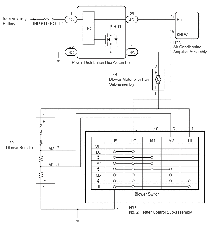
When the No. 2 heater control sub-assembly is operated, the power distribution box assembly will turn on to allow current to flow to the blower motor with fan sub-assembly and then the motor will start rotating. Operating the No. 2 heater control sub-assembly switches the current flow between the blower resistor and body ground, thus, shifting the rotation speed of the blower motor with fan sub-assembly.

If the airflow volume is low or the blower speed cannot be changed, the following factors may be the cause.

Symptom Factor
·

Blower does not operate at all. (No air comes out.)

·

Blower airflow volume cannot be changed.

·

Blower airflow volume is continuously weak.

·

Blower airflow volume is sometimes weak.


·

Power distribution box assembly

·

Blower motor with fan sub-assembly malfunction

·

Blower resistor malfunction

·

No. 2 heater control sub-assembly malfunction

·

Air conditioning amplifier assembly malfunction

·

Harness or connector


WIRING DIAGRAM

E437276E06
2.438,2.042 4.531,2.292 2.094,0.25 10 false Power Distribution Box Assembly 6,0.583 6.396,0.802 0.396,0.219 10 false HR 6,1.094 6.552,1.302 0.552,0.208 10 false SBLW 5.885,1.375 6.25,1.594 0.365,0.219 10 false H23 5.885,1.51 7.094,1.844 1.208,0.333 10 false Air Conditioning Amplifier Assembly 3.719,2.448 4.052,2.667 0.333,0.219 10 false H29 3.708,2.615 5.125,2.958 1.417,0.344 10 false Blower Motor with Fan Sub-assembly 5.781,0.49 6.094,0.688 0.313,0.198 10 false 21 5.76,0.99 6.073,1.188 0.313,0.198 10 false 15 4.385,0.594 4.677,0.813 0.292,0.219 10 false 4C 5.26,2.177 5.573,2.375 0.313,0.198 10 false 2 5.24,3.104 5.552,3.302 0.313,0.198 10 false 1 4.458,4.708 4.969,4.927 0.51,0.219 10 false LO 5.094,4.698 5.604,4.917 0.51,0.219 10 false M1 5.719,4.698 6.229,4.917 0.51,0.219 10 false M2 6.385,4.698 6.896,4.917 0.51,0.219 10 false HI 3.271,6.281 3.781,6.5 0.51,0.219 10 false HI 3.25,5.885 3.76,6.104 0.51,0.219 10 false M2 3.271,5.49 3.781,5.708 0.51,0.219 10 false M1 3.26,5.094 3.771,5.313 0.51,0.219 10 false LO 3.219,4.896 3.729,5.115 0.51,0.219 10 false OFF 4.594,4.313 4.813,4.5 0.219,0.188 10 false 3 5.229,4.302 5.448,4.49 0.219,0.188 10 false 10 6.5,4.292 6.719,4.51 0.219,0.219 10 false 1 5.865,4.302 6.104,4.5 0.24,0.198 10 false 6 3.948,6.969 4.26,7.167 0.313,0.198 10 false 5 4.385,6.99 4.729,7.177 0.344,0.188 10 false H33 4.385,7.135 6.938,7.458 2.552,0.323 10 false No. 2 Heater Control Sub-assembly 1.938,4.948 2.104,5.167 0.167,0.219 10 false 2 1.448,3.833 1.667,4.031 0.219,0.198 10 false 4 1.448,6.292 1.656,6.51 0.208,0.219 10 false 1 1.917,5.51 2.083,5.74 0.167,0.229 10 false 3 1.448,4.063 1.969,4.281 0.521,0.219 10 false HI 1.646,5.521 1.948,5.74 0.302,0.219 10 false M1 1.646,4.969 1.948,5.188 0.302,0.219 10 false M2 1.469,6.063 1.688,6.292 0.219,0.229 10 false E 0.219,4.781 0.51,4.958 0.292,0.177 10 false H30 0.208,4.938 1.208,5.208 1,0.271 10 false Blower Resistor 5.26,2.385 5.573,2.583 0.313,0.198 10 false B 5.26,2.896 5.406,3.104 0.146,0.208 10 false L 4.573,6.521 5.5,6.729 0.927,0.208 10 false Blower Switch 3.958,6.74 4.469,6.958 0.51,0.219 10 false E 1.125,0.719 2.313,1.104 1.188,0.385 10 false INP STD NO. 1-1 0.094,0.552 0.969,0.906 0.875,0.354 10 false from Auxiliary Battery 3.875,4.708 4.385,4.927 0.51,0.219 10 false E 4.406,0.385 4.573,0.583 0.167,0.198 10 false 26 2.323,0.583 2.615,0.802 0.292,0.219 10 false 4G 2.385,0.385 2.552,0.583 0.167,0.198 10 false 1 4.406,1.698 4.698,1.917 0.292,0.219 10 false 4A 4.448,1.49 4.615,1.688 0.167,0.198 10 false 1 2.333,1.698 2.625,1.917 0.292,0.219 10 false 4C 2.354,1.49 2.646,1.708 0.292,0.219 10 false 25 2.958,0.885 3.219,1.115 0.26,0.229 10 false IC 3.875,0.813 4.177,1.042 0.302,0.229 10 false +B1

CAUTION / NOTICE / HINT

NOTICE:

Inspect the fuses for circuits related to this system before performing the following procedure.


PROCEDURE

1.CHECK DTC
a.

Check for DTCs.

Body Electrical > Power Distribution Box > Trouble Codes
50001 475
OK:

Power integration system DTCs are not output.


Result:
Proceed to
OK
NG


OK

2.INSPECT BLOWER MOTOR WITH FAN SUB-ASSEMBLY

NG

2.INSPECT BLOWER MOTOR WITH FAN SUB-ASSEMBLY
a.

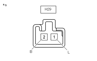
Disconnect the H29 blower motor with fan sub-assembly connector.

b.
E439700C01
1.438,0.208 1.979,0.469 0.542,0.26 1.125,1.76 1.479,1.396 true 2.365,1.781 1.99,1.396 true 0.104,0.104 0.385,0.385 0.281,0.281 10 false *a 1.063,1.781 1.302,2.01 0.24,0.229 10 false B 2.406,1.802 2.615,2.01 0.208,0.208 10 false L 1.594,0.26 2.052,0.458 0.458,0.198 10 false H29
*a Component without harness connected
(Blower Motor with Fan Sub-assembly)


Inspect the blower motor with fan sub-assembly.

OK:
Measurement Condition Specified Condition
Auxiliary battery positive (+) → Terminal 2 (B)
Auxiliary battery negative (-) → Terminal 1 (L)
Blower motor with fan sub-assembly operates smoothly


Result:
Proceed to
OK
NG


OK

3.INSPECT BLOWER RESISTOR

NG

REPLACE BLOWER MOTOR WITH FAN SUB-ASSEMBLY

3.INSPECT BLOWER RESISTOR


Result:
Proceed to
OK
NG


OK

4.INSPECT NO. 2 HEATER CONTROL SUB-ASSEMBLY

NG

4.INSPECT NO. 2 HEATER CONTROL SUB-ASSEMBLY

OK

5.CHECK HARNESS AND CONNECTOR (POWER DISTRIBUTION BOX ASSEMBLY - AIR CONDITIONING AMPLIFIER ASSEMBLY)

NG

5.CHECK HARNESS AND CONNECTOR (POWER DISTRIBUTION BOX ASSEMBLY - AIR CONDITIONING AMPLIFIER ASSEMBLY)
a.

Disconnect the 4C power distribution box assembly connector.


b.

Disconnect the H23 air conditioning amplifier assembly connector.


c.

Measure the resistance according to the value(s) in the table below.

Standard Resistance:
Tester Connection Condition Specified Condition
4C-26 - H23-21 (HR) Always Below 1 Ω
4C-26 or H23-21 (HR) - Other terminals and body ground Always 10 kΩ or higher


Result:
Proceed to
OK
NG


OK

6.CHECK HARNESS AND CONNECTOR (AIR CONDITIONING AMPLIFIER ASSEMBLY - NO. 2 HEATER CONTROL SUB-ASSEMBLY)

NG

REPAIR OR REPLACE HARNESS OR CONNECTOR

6.CHECK HARNESS AND CONNECTOR (AIR CONDITIONING AMPLIFIER ASSEMBLY - NO. 2 HEATER CONTROL SUB-ASSEMBLY)
a.

Measure the resistance according to the value(s) in the table below.

Standard Resistance:
Tester Connection Condition Specified Condition
H23-15 (SBLW) - H33-3 (LO) Always Below 1 Ω
H23-15 (SBLW) or H33-3 (LO) - Other terminals and body ground Always 10 kΩ or higher


Result:
Proceed to
OK
NG


OK

7.CHECK HARNESS AND CONNECTOR (BLOWER RESISTOR - NO. 2 HEATER CONTROL SUB-ASSEMBLY AND BODY GROUND)

NG

REPAIR OR REPLACE HARNESS OR CONNECTOR

7.CHECK HARNESS AND CONNECTOR (BLOWER RESISTOR - NO. 2 HEATER CONTROL SUB-ASSEMBLY AND BODY GROUND)
a.

Measure the resistance according to the value(s) in the table below.

Standard Resistance:
Tester Connection Condition Specified Condition
H30-2 (M2) - H33-6 (M2) Always Below 1 Ω
H30-3 (M1) - H33-10 (M1) Always Below 1 Ω
H30-4 (HI) - H33-1 (HI) Always Below 1 Ω
H30-1 (E) - Body ground Always Below 1 Ω
H33-5 (E) - Body ground Always Below 1 Ω
H30-2 (M2) or H33-6 (M2) - Other terminals and body ground Always 10 kΩ or higher
H30-3 (M1) or H33-10 (M1) - Other terminals and body ground Always 10 kΩ or higher
H30-4 (HI) or H33-1 (HI) - Other terminals and body ground Always 10 kΩ or higher


Result:
Proceed to
OK
NG


OK

8.CHECK HARNESS AND CONNECTOR (BLOWER MOTOR WITH FAN SUB-ASSEMBLY - NO. 2 HEATER CONTROL SUB-ASSEMBLY)

NG

REPAIR OR REPLACE HARNESS OR CONNECTOR

8.CHECK HARNESS AND CONNECTOR (BLOWER MOTOR WITH FAN SUB-ASSEMBLY - NO. 2 HEATER CONTROL SUB-ASSEMBLY)
a.

Measure the resistance according to the value(s) in the table below.

Standard Resistance:
Tester Connection Condition Specified Condition
H29-1 (L) - H33-1 (HI) Always Below 1 Ω
H29-1 (L) or H33-1 (HI) - Other terminals and body ground Always 10 kΩ or higher


Result:
Proceed to
OK
NG


OK

9.CHECK HARNESS AND CONNECTOR (POWER DISTRIBUTION BOX ASSEMBLY - BLOWER MOTOR WITH FAN SUB-ASSEMBLY)

NG

REPAIR OR REPLACE HARNESS OR CONNECTOR

9.CHECK HARNESS AND CONNECTOR (POWER DISTRIBUTION BOX ASSEMBLY - BLOWER MOTOR WITH FAN SUB-ASSEMBLY)
a.

Disconnect the 4A power distribution box assembly connector.


b.

Measure the resistance according to the value(s) in the table below.

Standard Resistance:
Tester Connection Condition Specified Condition
4A-1 - H29-2 (B) Always Below 1 Ω
4A-1 or H29-2 (B) - Other terminals and body ground Always 10 kΩ or higher


Result:
Proceed to
OK
NG


OK

REPLACE AIR CONDITIONING AMPLIFIER ASSEMBLY

NG

REPAIR OR REPLACE HARNESS OR CONNECTOR