HEATING / AIR CONDITIONING AIR CONDITIONING SYSTEM(for Gasoline Model with Manual Air Conditioning System) Heater Control Switch Circuit
DESCRIPTION
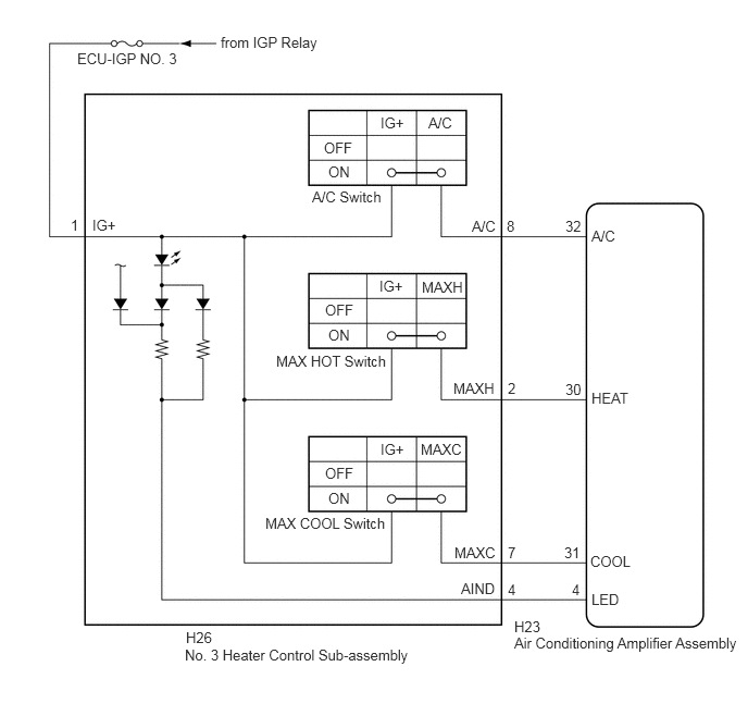
The No. 3 heater control sub-assembly is powered through the ECU-IGP NO. 3 fuse. The No. 3 heater control sub-assembly transmits operational signals of each switch to the air conditioning amplifier assembly.
| Symptom | Factor |
|---|---|
·
A/C switch indicator is abnormal ·
Hot air does not come out even though temperature control switch set to MAX HOT ·
Idle up not performed even though temperature control switch set to MAX COOL |
·
No. 3 heater control sub-assembly malfunction ·
Air conditioning amplifier assembly malfunction ·
Harness or connector |
WIRING DIAGRAM
CAUTION / NOTICE / HINT
- NOTICE:
-
Inspect the fuses for circuits related to this system before performing the following procedure.
PROCEDURE
Remove the No. 3 heater control sub-assembly.
Inspect the No. 3 heater control sub-assembly.
- Result:
Proceed to OK NG
OK
NG
Disconnect the H26 No. 3 heater control sub-assembly connector.
Measure the voltage according to the value(s) in the table below.
- Standard Voltage:
Tester Connection Switch Condition Specified Condition H26-1 (IG+) - Body ground Ignition switch ON 11 to 14 V H26-1 (IG+) - Body ground Ignition switch off Below 1 V
- Result:
Proceed to OK NG
OK
NG
Choose the problem to be inspected.
- Result:
Result Proceed to A/C switch indicator is abnormal A Hot air does not come out even though temperature control switch set to MAX HOT B Idle up not performed even though temperature control switch set to MAX COOL C
A
B
C
Disconnect the H26 No. 3 heater control sub-assembly connector.
Disconnect the H23 air conditioning amplifier assembly connector.
Measure the resistance according to the value(s) in the table below.
- Standard Resistance:
Tester Connection Condition Specified Condition H26-8 (A/C) - H23-32 (A/C) Always Below 1 Ω H26-4 (AIND) - H23-4 (LED) Always Below 1 Ω H26-8 (A/C) or H23-32 (A/C) - Other terminals and body ground Always 10 kΩ or higher H26-4 (AIND) or H23-4 (LED) - Other terminals and body ground Always 10 kΩ or higher
- Result:
Proceed to OK NG
OK
NG
Disconnect the H26 No. 3 heater control sub-assembly connector.
Disconnect the H23 air conditioning amplifier assembly connector.
Measure the resistance according to the value(s) in the table below.
- Standard Resistance:
Tester Connection Condition Specified Condition H26-2 (MAXH) - H23-30 (HEAT) Always Below 1 Ω H26-4 (AIND) - H23-4 (LED) Always Below 1 Ω H26-2 (MAXH) or H23-30 (HEAT) - Other terminals and body ground Always 10 kΩ or higher H26-4 (AIND) or H23-4 (LED) - Other terminals and body ground Always 10 kΩ or higher
- Result:
Proceed to OK NG
OK
NG
Disconnect the H26 No. 3 heater control sub-assembly connector.
Disconnect the H23 air conditioning amplifier assembly connector.
Measure the resistance according to the value(s) in the table below.
- Standard Resistance:
Tester Connection Condition Specified Condition H26-7 (MAXC) - H23-31 (COOL) Always Below 1 Ω H26-4 (AIND) - H23-4 (LED) Always Below 1 Ω H26-7 (MAXC) or H23-31 (COOL) - Other terminals and body ground Always 10 kΩ or higher H26-4 (AIND) or H23-4 (LED) - Other terminals and body ground Always 10 kΩ or higher
- Result:
Proceed to OK NG
OK
NG