P910 HYBRID TRANSMISSION / TRANSAXLE HYBRID TRANSAXLE SYSTEM ON-VEHICLE INSPECTION
CAUTION / NOTICE / HINT
- CAUTION:
-
-
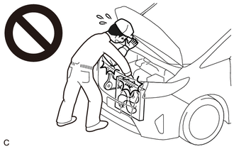
To prevent injury due to contact with an operating V-ribbed belt or cooling fan, keep your hands and clothing away from the V-ribbed belt and cooling fans when working in the engine compartment with the engine running or the ignition switch ON.
PROCEDURE

 51451A
1.REMOVE CENTER ENGINE UNDER COVER
51442C
2.REMOVE ENGINE UNDER COVER LH
3.INSPECT TRANSAXLE FLUID PRESSURE
- NOTICE:
-
Make sure to perform the following inspection after inspecting and adjusting the engine.
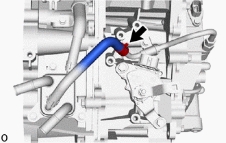
Slide the clip and disconnect the No. 1 motor cooling hose from the No. 1 motor cooling pipe.
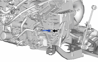
Loosen the flare nut of the No. 1 motor cooling pipe and disconnect the No. 1 motor cooling pipe from the union.
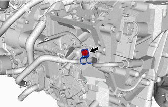
Remove the bolt and No. 1 oil cooler tube clamp from the hose bracket.
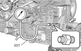
Install SST to the union.
- SST
- 09993-19015 (09993-00020, 09993-00030)
Put the engine in Inspection Mode (Maintenance Mode).
Click hereGeneral>INTRODUCTION>REPAIR INSTRUCTION>INSPECTION MODE PROCEDURE
Measure the hybrid transaxle fluid pressure.
- Reference:
Maintenance Mode Engine Idle Speed Hybrid Transaxle Fluid Temperature Hybrid Transaxle Fluid Pressure 950 to 1050 rpm 20 to 50°C (68 to 122°F) 9.8 kPa (0.1 kgf/cm2, 1 psi) or more
- NOTICE:
-
Be sure to cancel maintenance mode immediately after the hybrid transaxle fluid pressure check is completed.
Remove SST from the union.
Temporarily connect a new No. 1 motor cooling pipe to the union with the flare nut.
Install the No. 2 oil cooler tube clamp to the No. 1 transmission control cable bracket with the bolt.
- Torque:
- 8.0 N*m (82 kgf*cm, 71 in.*lbf)
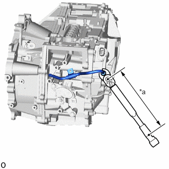
| *a | Torque Wrench Fulcrum Length |
Using a 17 mm union nut wrench, tighten the flare nut to connect the No. 1 motor cooling pipe.
- Torque:
- Specified Tightening Torque : 34.3 N*m (350 kgf*cm, 25 ft.*lbf)
- HINT:
- ·
Calculate the torque wrench reading when changing the fulcrum length of the torque wrench.
Click hereGeneral>INTRODUCTION>REPAIR INSTRUCTION>PRECAUTION
·When using a 17 mm union nut wrench (fulcrum length of 30 mm (1.18 in.)) + torque wrench (fulcrum length of 180 mm (7.09 in.)): 29.4 N*m (300 kgf*cm, 22 ft.*lbf)
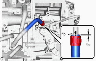
| *a | 2 to 7 mm (0.0787 to 0.276 in.) |
| *b | Paint Mark |
Connect the No. 1 motor cooling hose to the No. 1 motor cooling pipe and slide the clip to secure it.
- NOTICE:
-
Make sure to align the paint mark on the No. 1 motor cooling pipe with the paint mark on the No. 1 motor cooling hose.
51442C
4.INSTALL ENGINE UNDER COVER LH
51451A
5.INSTALL CENTER ENGINE UNDER COVER