CLUTCH CLUTCH PEDAL SWITCH INSTALLATION
PROCEDURE

 88280A
1.INSTALL CLUTCH SWITCH ASSEMBLY (for LHD)
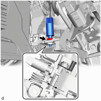
| *a | Clearance |
Install the clutch switch assembly to the clutch pedal support sub-assembly with the nut.
- Torque:
- 17.15 N*m (175 kgf*cm, 13 ft.*lbf)
Connect the clutch switch assembly connector.
Without depressing the clutch pedal, check that the clearance shown in the illustration is as specified.
- Standard clearance:
3.2 to 3.6 mm (0.126 to 0.142 in.)
88280A
2.INSTALL CLUTCH SWITCH ASSEMBLY (for RHD)
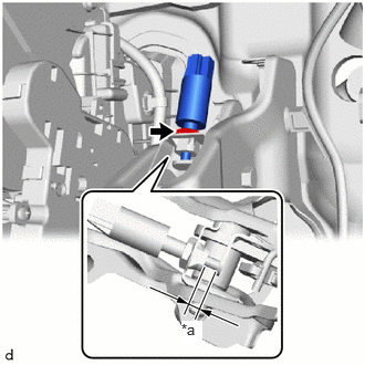
| *a | Clearance |
Install the clutch switch assembly to the clutch pedal support sub-assembly with the nut.
- Torque:
- 15.7 N*m (160 kgf*cm, 12 ft.*lbf)
Connect the clutch switch assembly connector.
Without depressing the clutch pedal, check that the clearance shown in the illustration is as specified.
- Standard clearance:
1.8 to 2.8 mm (0.071 to 0.110 in.)
3.INSTALL CLUTCH PEDAL SUPPORT ASSEMBLY (for LHD)
4.INSTALL CLUTCH PEDAL SUPPORT ASSEMBLY (for RHD)
31453A
5.INSTALL CLUTCH MASTER CYLINDER PUSH ROD CLEVIS WITH HOLE PIN (for LHD)
31453A
6.INSTALL CLUTCH MASTER CYLINDER PUSH ROD CLEVIS WITH HOLE PIN (for RHD)
7.INSTALL STEERING COLUMN ASSEMBLY (for RHD)
84520
8.INSTALL CLUTCH START SWITCH ASSEMBLY
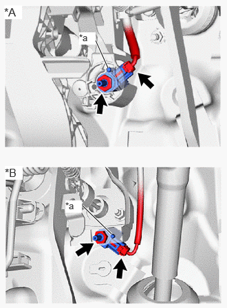
| *A | for LHD |
| *B | for RHD |
| *a | Protrusion |
Install the clutch start switch assembly to the clutch pedal support sub-assembly with the nut.
- Torque:
- for LHD : 15.68 N*m (160 kgf*cm, 12 ft.*lbf)
- for RHD : 15.7 N*m (160 kgf*cm, 12 ft.*lbf)
- NOTICE:
- ·
Insert the protrusion of the clutch start switch assembly into the hole in the clutch pedal support sub-assembly.
·To prevent damage to the clutch start switch assembly, make sure not to rotate it during installation.
Connect the clutch start switch assembly connector.
55606
9.INSTALL NO. 1 INSTRUMENT PANEL UNDER COVER SUB-ASSEMBLY
10.INSPECT CLUTCH START SYSTEM
11. INITIALIZATION AFTER RECONNECTING BATTERY TERMINAL
Click hereGeneral>SETUP>WHEN DISCONNECTING OR RECONNECTING BATTERY TERMINAL>WORK PROCEDURE
- HINT:
-
When disconnecting and reconnecting the battery, there is an automatic learning function that completes learning when the respective system is used.
-
Click hereGeneral>SETUP>WHEN DISCONNECTING OR RECONNECTING BATTERY TERMINAL>AUTOMATIC LEARNING CHART