1KR-FE ENGINE CONTROL THROTTLE BODY INSTALLATION
PROCEDURE

 22271A
1.INSTALL THROTTLE BODY GASKET
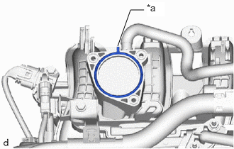
| *a | Protrusion |
Install a new throttle body gasket to the intake manifold with the protrusion of the throttle body gasket oriented as shown in the illustration.
22030
2.INSTALL THROTTLE BODY WITH MOTOR ASSEMBLY
Using an 8 mm socket wrench, install the throttle body with motor assembly to the intake manifold with the 3 bolts.
- Torque:
- 10 N*m (102 kgf*cm, 7 ft.*lbf)
- NOTICE:
-
If the throttle body with motor assembly has been struck or dropped, replace it.
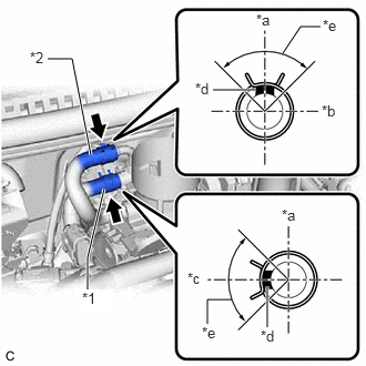
| *1 | No. 1 Water By-pass Hose Assembly |
| *2 | No. 2 Water By-pass Hose Assembly |
| *a | Top |
| *b | Front of Vehicle |
| *c | Rear of Vehicle |
| *d | Paint Mark |
| *e | 90° (Claw of Clip Location) |
Connect the No. 1 water by-pass hose assembly and No. 2 water by-pass hose assembly to the throttle body with motor assembly and slide the 2 clips to secure them.
- NOTICE:
-
Make sure to position each clip as shown in the illustration.
Connect the throttle body with motor assembly connector.
3.INSTALL AIR CLEANER CAP WITH AIR CLEANER HOSE
Set the air cleaner cap with air cleaner hose on the throttle body with motor assembly, No. 2 ventilation hose and cylinder head cover sub-assembly.
Connect the No. 2 ventilation hose to the cylinder head cover sub-assembly.
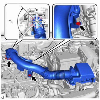
| *a | Rear of Vehicle |
| *b | Left Side of Vehicle |
| *c | 90° (Claw of Clip Location) |
Connect the air cleaner hose to the throttle body with motor assembly and slide the hose clamp to secure them.
Install the air cleaner cap with air cleaner hose with the 2 bolts.
- Torque:
- 7.8 N*m (80 kgf*cm, 69 in.*lbf)
Engage the 2 guides and 2 clamps.
4.ADD ENGINE COOLANT
5.INSPECT FOR COOLANT LEAK
6.PERFORM INITIALIZATION
- NOTICE:
- ·
Be sure to perform this procedure after removing and reinstalling the throttle body with motor assembly or any throttle body with motor assembly components.
·Perform the following procedure after replacing the throttle body with motor assembly or any throttle body with motor assembly components. The following procedure should also be performed if the throttle body with motor assembly is cleaned.
Perform "electronic throttle learning".
Click hereEngine / Hybrid System>1KR-FE (ENGINE CONTROL)>SFI SYSTEM>INITIALIZATION