BRAKE (REAR) REAR BRAKE(for TMC Made) INSTALLATION
PROCEDURE

 47570
1.INSTALL REAR WHEEL BRAKE CYLINDER ASSEMBLY
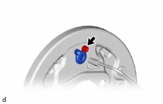
Install the rear wheel brake cylinder assembly with the bolt.
- Torque:
- 9.8 N*m (100 kgf*cm, 87 in.*lbf)
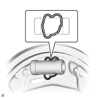

|
Seal Packing |
Clean and degrease the exterior of the mounting surface between the backing plate and the rear wheel brake cylinder assembly around its entire circumference.
- NOTICE:
-
Clean away all oil, moisture, dirt, etc. from the mounting surface.
Inside the brake drum, apply seal packing to the exterior of the rear wheel brake cylinder assembly mounting surface around its entire circumference.
- Seal Packing:
Toyota Genuine Seal Packing Black, Three Bond 1207B or equivalent
- NOTICE:
-
After installation, do not move the rear wheel brake cylinder assembly for at least 2 hours.
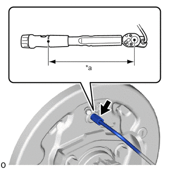
| *a | Torque Wrench Fulcrum Length |
Using a union nut wrench 10 mm, connect the brake tube.
- Torque:
- Specified tightening torque : 15.2 N*m (155 kgf*cm, 11 ft.*lbf)
- NOTICE:
- ·
Do not kink or damage the brake line.
·Do not allow any foreign matter such as dirt or dust to enter the brake line from the connecting parts.
- HINT:
- ·
Calculate the torque wrench reading when changing the fulcrum length of the torque wrench.
Click hereGeneral>INTRODUCTION>REPAIR INSTRUCTION>PRECAUTION
·When using a union nut wrench (fulcrum length of 22 mm (0.866 in.)) + torque wrench (fulcrum length of 162 mm (6.38 in.)): 13.4 N*m (137 kgf*cm, 10 ft.*lbf)
47644A
2.INSTALL REAR BRAKE AUTOMATIC ADJUST LEVER
Install the automatic adjust lever and automatic adjust lever tension spring to the front brake shoe.
04495
3.INSTALL REAR BRAKE SHOE KIT
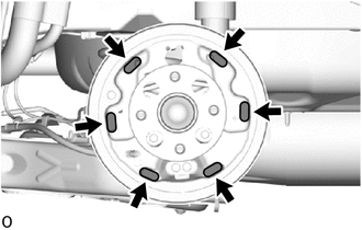

|
High Temperature Grease |
Apply high temperature grease to the surface of the backing plate which is in contact with the shoe.
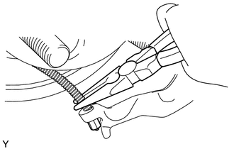
Using needle-nose pliers, install the No. 3 parking brake cable assembly to the rear brake parking brake shoe lever sub-assembly.
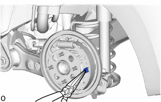
Using needle-nose pliers, install the rear brake shoe, shoe hold down spring pin, shoe hold down spring and shoe hold down spring cup.
|
|
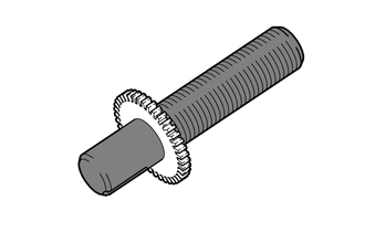
High Temperature Grease |
Apply high temperature grease to the adjusting bolt.
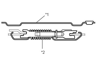
| *1 | Backing Plate |
| *2 | Rear Brake Strut Kit |
Install the parking brake shoe strut set as shown in the illustration.
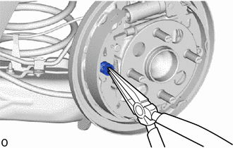
Using needle-nose pliers, install the front brake shoe, shoe hold down spring pin, shoe hold down spring and shoe hold down spring cup.
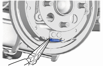
Using a needle-nose plier, install the tension spring to the front brake shoe and rear brake shoe.
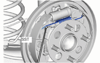
Using SST, install the shoe return spring to the front brake shoe.
- SST
- 09921-00011
- NOTICE:
-
Do not damage the wheel cylinder boot.
42431D
4.INSPECT BRAKE DRUM
Inspect that each part is installed properly as shown in the illustration.
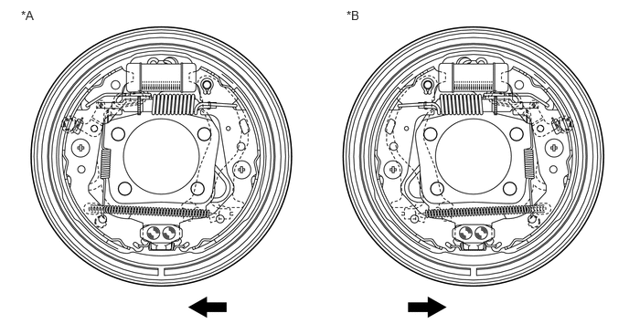
| *A | for LH Side | *B | for RH Side |

|
Front of the Vehicle | - | - |
- NOTICE:
-
There should be no oil or grease adhering to the friction surfaces of the shoe lining or the drum.
42431D
5.INSTALL BRAKE DRUM
Install the rear brake drum.
6.ADJUST REAR DRUM BRAKE SHOE CLEARANCE
Provisionally install the hub nuts.
Remove the shoe adjusting hole plug.
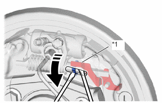
| *1 | Automatic Adjust Lever |

|
Expand |
Using a screwdriver, turn the adjuster to expand the shoe until the drum locks.
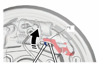
| *1 | Automatic Adjust Lever |
|
|
Contract |
Hold the automatic adjust lever away from the adjuster, and contract the brake shoe by turning the adjust bolt using another screwdriver until the drum can rotate smoothly.
Install the shoe adjusting hole plug.
7.BLEED BRAKE LINE
for HV Model:
Click hereBrake>BRAKE SYSTEM (OTHER)>BRAKE FLUID (for HV Model TMC Made)>BLEEDING
for Gasoline Model:
Click hereBrake>BRAKE SYSTEM (OTHER)>BRAKE FLUID (for Gasoline Model)>BLEEDING
8.BLEED CLUTCH LINE (for Manual Transmission)
for C551
Click hereDrivetrain>CLUTCH>CLUTCH SYSTEM (for C551)>BLEEDING
for EC6A
Click hereDrivetrain>CLUTCH>CLUTCH SYSTEM (for EC6E)>BLEEDING
9.INSTALL REAR WHEEL
10.ADJUST PARKING BRAKE
11.CONNECT CABLE TO NEGATIVE AUXILIARY BATTERY TERMINAL (for HV Model)
12. INITIALIZATION AFTER RECONNECTING AUXILIARY BATTERY TERMINAL (for HV Model)
Click hereGeneral>SETUP>WHEN DISCONNECTING OR RECONNECTING BATTERY TERMINAL>WORK PROCEDURE
- HINT:
-
When disconnecting and reconnecting the auxiliary battery, there is an automatic learning function that completes learning when the respective system is used.
-
Click hereGeneral>SETUP>WHEN DISCONNECTING OR RECONNECTING BATTERY TERMINAL>AUTOMATIC LEARNING CHART