EC6E MANUAL TRANSMISSION / TRANSAXLE MANUAL TRANSAXLE ASSEMBLY(When Not Using the Engine Support Bridge) REMOVAL
CAUTION / NOTICE / HINT
The necessary procedures (adjustment, calibration, initialization or registration) that must be performed after parts are removed and installed, or replaced during manual transaxle assembly removal/installation are shown below.
| Replaced Part or Performed Procedure | Necessary Procedure | Effect/Inoperative Function when Necessary Procedure not Performed | Link |
|---|---|---|---|
| Disconnect cable from negative auxiliary battery terminal | Memorize steering angle neutral point | Parking assist monitor system | ( ) |
·
Replacement of engine assembly ·
Air leaks from intake system is repaired ·
Gas leaks from exhaust system is repaired |
Inspection After Repair | ·
Poor idle, etc. ·
Engine start function, etc. |
()
|
| Front wheel alignment adjustment | Calibration | ·
VSC disabled or malfunctions ·
DTCs are stored ·
Slip indicator light illuminates ·
ABS warning light illuminates |
for TMC Made:
( )
for TMMF Made: ( )
|
| Suspension, tires, etc. | ·
Ultrasonic sensor detection angle ·
Ultrasonic sensor detection angle registration |
Parking support brake system | ()
|
| Rear television camera assembly optical axis (Back camera position setting) | Parking assist monitor system | ()
|
- CAUTION:
- ·
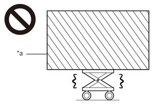 0.542,1.115 0.958,1.115 false 0.344,1.01 0.656,1.208 0.313,0.198 10 false *a
*a Heavy object exceeding the capacity of the engine lifter
Because the weight of the engine with transaxle assembly is extremely heavy, make sure to follow the work procedures described in the repair manual.
·If work is not performed according to the procedures described in the repair manual, there is a danger that the engine lifter could drop and components could fall down.
- ·
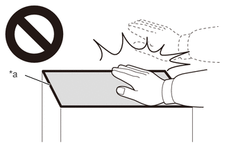 0.375,1.135 0.75,1.281 true 0.135,1.031 0.448,1.229 0.313,0.198 10 false *a
*a High temperature areas
Do not touch the engine or exhaust manifold converter sub-assembly when they are hot.
·Touching the engine or exhaust manifold converter sub-assembly when they are hot could result in burns.
- ·
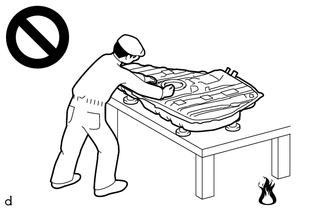
Never perform work on fuel system components near any possible ignition sources.
·Vaporized fuel could ignite, resulting in a serious accident.
- ·
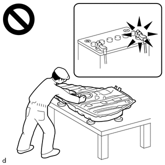
Do not perform work on fuel system components without first disconnecting the cable from the negative (-) auxiliary battery terminal.
·Sparks could cause vaporized fuel to ignite, resulting in a serious accident.
- NOTICE:
-
This procedure includes the removal of small-head bolts. Refer to Small-Head Bolts of Basic Repair Hint to identify the small-head bolts.
-
Click hereGeneral>INTRODUCTION>REPAIR INSTRUCTION>PRECAUTION
- HINT:
-
When the cable is disconnected / reconnected to the auxiliary battery terminal, systems temporarily stop operating. However, each system has a function that completes learning the first time the system is used.
- ·
Learning completes when vehicle is driven
Effect/Inoperative Function When Necessary Procedures are not Performed Necessary Procedures Link Lane tracing assist system Drive the vehicle straight ahead at 35 km/h (22 mph) or more for 5 second or more. ( )
Pre-collision system
·Learning completes when vehicle is operated normally
Effect/Inoperative Function When Necessary Procedures are not Performed Necessary Procedures Link Power door lock control system
·Back door opener
Perform door unlock operation with door control switch or electrical key transmitter sub-assembly switch. ( )
Air conditioning system After the ignition switch is turned to ON, the servo motor standard position is recognized. -
PROCEDURE

 1.REMOVE ENGINE ASSEMBLY WITH TRANSAXLE
2.INSTALL ENGINE HANGERS
28100
3.REMOVE STARTER ASSEMBLY
4.DISCONNECT ENGINE WIRE
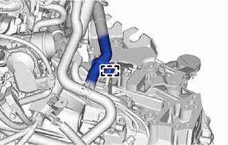
Disengage the clamp.
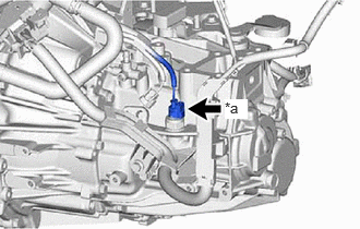
| *a | Back-up Light Switch Assembly Connector |
Disconnect the back-up light switch assembly connector.
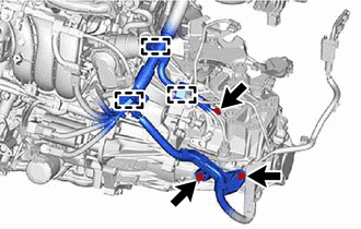
Remove the 3 bolts.
Disengage the 3 clamps.
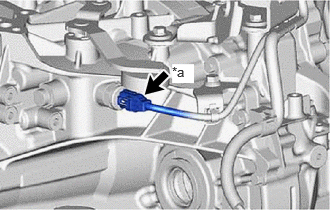
| *a | Neutral Position Switch Connector |
Disconnect the neutral position switch connector.
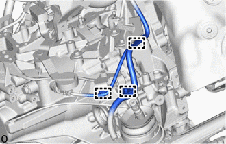
Disengage the 3 clamps.
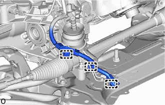
Disengage the 3 clamps.
43409E
5.REMOVE DRIVE SHAFT HEAT INSULATOR SUB-ASSEMBLY
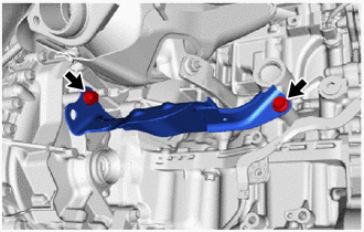
Remove the 2 bolts and drive shaft heat insulator sub-assembly.
30300
6.REMOVE MANUAL TRANSAXLE ASSEMBLY
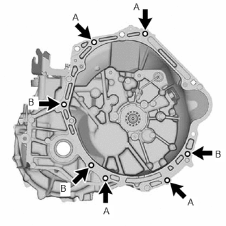
Remove the 7 bolts and manual transaxle assembly from the engine assembly.
- HINT:
- ·
Bolt (A): Remove from the manual transaxle assembly side.
·Bolt (B): Remove from the engine assembly side.
51201
7.REMOVE FRONT SUSPENSION CROSSMEMBER SUB-ASSEMBLY
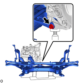
Remove the bolt and front suspension crossmember sub-assembly from the No. 2 engine moving control rod.
12364B
8.REMOVE NO. 2 ENGINE MOVING CONTROL ROD
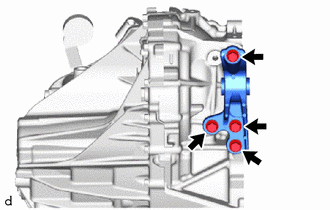
Remove the 4 bolts and No. 2 engine moving control rod from the front transaxle case.
31483
9.REMOVE BLEEDER CLUTCH RELEASE TUBE
31484
10.REMOVE CLUTCH FLEXIBLE HOSE BRACKET
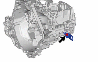
Remove the bolt and clutch flexible hose bracket from the manual transmission case.
31407B
11.REMOVE CLUTCH RELEASE BLEEDER SUB-ASSEMBLY
31400
12.REMOVE CLUTCH RELEASE CYLINDER WITH BEARING ASSEMBLY
31483
13.REMOVE CLUTCH RELEASE CYLINDER TO BLEEDER TUBE
87121V
14.REMOVE HEATER BRACKET
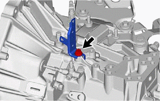
Remove the bolt and heater bracket from the manual transmission case.
15.REMOVE WIRE HARNESS CLAMP BRACKET
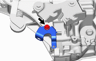
Remove the bolt and wire harness clamp bracket from the manual transmission case.
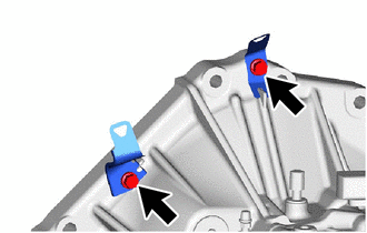
Remove the 2 bolts and 2 wire harness clamp brackets from the front transaxle (MTM) case.
35150D
16.REMOVE TRANSMISSION CASE PLUG ASSEMBLY
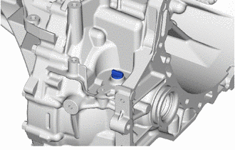
Remove the transmission case plug assembly from the manual transaxle assembly
- HINT:
-
It is not necessary to remove the manual transaxle assembly.