BRAKE CONTROL / DYNAMIC CONTROL SYSTEMS ELECTRONICALLY CONTROLLED BRAKE SYSTEM(for Gasoline Model TMMF Made) C050079 Left Front Wheel Speed Sensor Mechanical Linkage Failure
DESCRIPTION
The skid control ECU (brake actuator assembly) calculates the various wheel speeds based on signals from each type of sensor.
By comparing the calculated wheel speed values with the output values of each wheel speed sensor signal, the skid control ECU (brake actuator assembly) checks that each wheel speed sensor is functioning correctly.
| DTC No. | Detection Item | DTC Detection Condition | Trouble Area | DTC Output from |
|---|---|---|---|---|
| C050079 | Left Front Wheel Speed Sensor Mechanical Linkage Failure | At a vehicle speed of 14 km/h (9 mph) or more, the wheel speed sensor signal output value continuously differs from the control value calculated by the skid control ECU. | ·
Front speed sensor LH ·
Speed sensor installation ·
Front speed sensor rotor LH (front axle hub sub-assembly LH) |
Brake |
CAUTION / NOTICE / HINT
- NOTICE:
- ·
After replacing or removing and installing a speed sensor, perform Dealer Mode (Signal Check) inspection to confirm that the speed sensors are operating correctly.
·After replacing or removing and installing a speed sensor rotor, perform Dealer Mode (Signal Check) inspection to confirm that the speed sensors are operating correctly.
- HINT:
-
The front speed sensor rotor LH is incorporated into the front axle hub sub-assembly LH.
-
If the front speed sensor rotor LH needs to be replaced, replace the front axle hub sub-assembly LH.
PROCEDURE
Operate the GTS to read the DTCs.
- Chassis > Brake > Trouble Codes
- 50001 435
Check the details of the DTCs.
- HINT:
-
When DTC C050018, C050019, C05001F, C050023 and/or C050024 are output together with DTC C050079, inspect and repair the trouble areas indicated by DTC C050018, C050019, C05001F, C050023 and/or C050024 first.
- Result:
Result Proceed to Only C050079 is output A C050018, C050019, C05001F, C050023 and/or C050024 are output together B
A
B
Check that all 4 tires are of correct size, are inflated to the correct pressure, and do not show excessive signs of wear.
- HINT:
-
If a tire is deformed or an incorrectly sized tire or wheel is installed, this DTC may be stored.
-
Click hereSuspension>TIRE / WHEEL>TIRE AND WHEEL SYSTEM>INSPECTION
- Result:
Proceed to NEXT
NEXT
Pre-procedure1
Using the GTS, select a DTC to display the Freeze Frame Data.
- HINT:
-
Using to the freeze frame data, the approximate vehicle conditions that were present when the DTC was stored can be determined.
Procedure1
Read the freeze frame data of DTC C050079.
- Chassis > Brake
-
Tester Display Measurement Item Range Normal Condition Diagnostic Note FR Wheel Speed Front wheel speed sensor RH reading Min.: 0.0 km/h (0.0 mph)
Max.: 6553.5 km/h (4072 mph)Vehicle stopped: 0.0 km/h (0.0 mph) When driving at constant speed: No large fluctuations FL Wheel Speed Front wheel speed sensor LH reading Min.: 0.0 km/h (0.0 mph)
Max.: 6553.5 km/h (4072 mph)Vehicle stopped: 0.0 km/h (0.0 mph) When driving at constant speed: No large fluctuations RR Wheel Speed Rear wheel speed sensor RH reading Min.: 0.0 km/h (0.0 mph)
Max.: 6553.5 km/h (4072 mph)Vehicle stopped: 0.0 km/h (0.0 mph) When driving at constant speed: No large fluctuations RL Wheel Speed Rear wheel speed sensor LH reading Min.: 0.0 km/h (0.0 mph)
Max.: 6553.5 km/h (4072 mph)Vehicle stopped: 0.0 km/h (0.0 mph) When driving at constant speed: No large fluctuations Vehicle Speed Maximum wheel speed sensor reading Min.: 0.0 km/h (0.0 mph)
Max.: 6553.5 km/h (4072 mph)Vehicle stopped: 0.0 km/h (0.0 mph) When driving at constant speed: No large fluctuations
- Chassis > Brake > DTC(C050079) > Freeze Frame Data
-
Tester Display FR Wheel Speed FL Wheel Speed RR Wheel Speed RL Wheel Speed Vehicle Speed - 50040 435 13,14,15,16,51 C050079
Post-procedure1
None
- Result:
Proceed to NEXT
NEXT
Pre-procedure1
Start the engine.
Procedure1
Select the Data List on the GTS.
- Chassis > Brake > Data List
-
Tester Display Measurement Item Range Normal Condition Diagnostic Note FR Wheel Speed Front wheel speed sensor RH reading Min.: 0.0 km/h (0.0 mph)
Max.: 6553.5 km/h (4072 mph)Vehicle stopped: 0.0 km/h (0.0 mph) When driving at constant speed: No large fluctuations FL Wheel Speed Front wheel speed sensor LH reading Min.: 0.0 km/h (0.0 mph)
Max.: 6553.5 km/h (4072 mph)Vehicle stopped: 0.0 km/h (0.0 mph) When driving at constant speed: No large fluctuations RR Wheel Speed Rear wheel speed sensor RH reading Min.: 0.0 km/h (0.0 mph)
Max.: 6553.5 km/h (4072 mph)Vehicle stopped: 0.0 km/h (0.0 mph) When driving at constant speed: No large fluctuations RL Wheel Speed Rear wheel speed sensor LH reading Min.: 0.0 km/h (0.0 mph)
Max.: 6553.5 km/h (4072 mph)Vehicle stopped: 0.0 km/h (0.0 mph) When driving at constant speed: No large fluctuations Vehicle Speed Maximum wheel speed sensor reading Min.: 0.0 km/h (0.0 mph)
Max.: 6553.5 km/h (4072 mph)Vehicle stopped: 0.0 km/h (0.0 mph) When driving at constant speed: No large fluctuations
- Chassis > Brake > Data List
-
Tester Display FR Wheel Speed FL Wheel Speed RR Wheel Speed RL Wheel Speed Vehicle Speed - 50003 435 13,14,15,16,36
Perform a road test under the same malfunction conditions recreated based on the Freeze Frame Data or customer problem analysis.
Check the value of Wheel Speed and Vehicle Speed.
- OK:
The value of each Wheel Speed and Vehicle Speed changes in accordance with vehicle speed and the maximum difference between any 2 sensors is less than 6%.
- HINT:
-
If the result of the road test is within the specified range, it is possible that this DTC was stored due to a particular situation.
Post-procedure1
Turn the ignition switch off.
- Result:
Proceed to OK NG
OK
Click hereGeneral>INTRODUCTION>HOW TO TROUBLESHOOT ECU CONTROLLED SYSTEMS>HOW TO PROCEED WITH TROUBLESHOOTING
NG
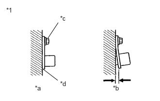
| *1 | Front Speed Sensor LH |
| *a | Correct |
| *b | Incorrect |
| *c | 8.5 N*m (87 kgf*cm, 75 in.*lbf) |
| *d | No clearance |
Check the front speed sensor LH installation.
- OK:
There is no clearance between the front speed sensor LH and front steering knuckle LH.
The installation bolt is tightened properly.
- Torque:
- 8.5 N*m (87 kgf*cm, 75 in.*lbf)
- Result:
Proceed to OK NG
OK
NG
Pre-procedure1
Remove the front speed sensor LH.
Click hereBrake>BRAKE CONTROL / DYNAMIC CONTROL SYSTEMS>FRONT SPEED SENSOR>REMOVAL
Procedure1
Check the front speed sensor LH.
- OK:
The front speed sensor LH tip is free of scratches, oil, and foreign matter.
- NOTICE:
- ·
If there is oil or foreign matter on the front speed sensor LH, clean the front speed sensor LH.
·If the front speed sensor LH is damaged, replace the front speed sensor LH with a new one.
Post-procedure1
Turn the ignition switch off.
- Result:
Result Proceed to OK A NG (The front speed sensor LH is damaged.) B NG (There is foreign matter on the front speed sensor LH.) C
A
B
C
Pre-procedure1
Remove the component with the front speed sensor rotor LH.
Click hereDrivetrain>AXLE AND DIFFERENTIAL>FRONT AXLE HUB (for TMMF Made)>REMOVAL
Procedure1
Check the front speed sensor rotor LH.
- OK:
The front speed sensor rotor LH is free of scratches, oil, and foreign matter.
- NOTICE:
- ·
If there is oil or foreign matter on the front speed sensor rotor LH, clean the front speed sensor rotor LH.
·Do not use parts cleaner when cleaning the front speed sensor rotor LH.
·If the front speed sensor rotor LH is damaged, replace the front axle hub sub-assembly LH with a new one.
Post-procedure1
None
- Result:
Result Proceed to OK A NG (The front speed sensor rotor LH is damaged.) B NG (There is foreign matter on the front speed sensor rotor LH.) C
A
B
C