HEATING / AIR CONDITIONING AIR CONDITIONING SYSTEM(for Gasoline Model with Automatic Air Conditioning System) PTC Heater Circuit
DESCRIPTION
The air conditioning amplifier assembly sends operation signals to the No. 2 semiconductor power integration ECU when quick heater assembly operation conditions are met. Based on the signals from the air conditioning amplifier assembly, the No. 2 semiconductor power integration ECU turn on, and power is supplied to the quick heater assembly installed in the air conditioning radiator assembly.
- HINT:
- ·
When all drive conditions are fulfilled, 3 quick heater assembly elements are driven.
·The number of quick heater assembly elements driven varies depending on the engine coolant temperature.
If the heating performance is poor when it is cold, the following factors may be the cause.
| Symptom | Factor |
|---|---|
| Heating performance is poor when it is cold | ·
No. 2 semiconductor power integration ECU malfunction ·
Main body ECU (multiplex network body ECU) malfunction ·
Quick heater assembly malfunction ·
Air conditioning amplifier assembly malfunction ·
Harness and connector |
WIRING DIAGRAM
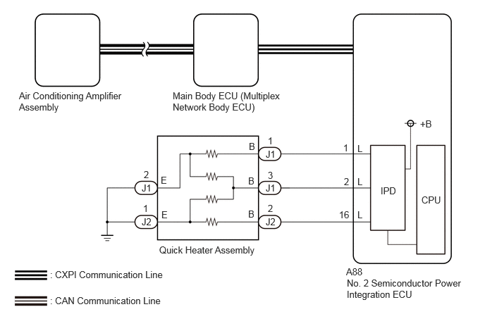
CAUTION / NOTICE / HINT
- NOTICE:
-
The air conditioning system uses the CAN and CXPI communication system. Inspect the communication functions by following How to Proceed with Troubleshooting. Troubleshoot the air conditioning system after confirming that the communication systems are functioning properly.
PROCEDURE
Using the GTS, check if the power integration system is functioning normally.
Click herePower Source / Network>POWER DISTRIBUTION>POWER INTEGRATION SYSTEM>DTC CHECK / CLEAR
- Result:
Result Proceed to DTC is not output A DTC is output B
A
B
Disconnect the J1 and J2 quick heater assembly connectors.
Perform the Active Test according to the display on the GTS.
- Body Electrical > Air Conditioner > Active Test
-
Tester Display Measurement Item Control Range Diagnostic Note PTC Heater Quick heater assembly Min.: 0
Max.: 3-
- Body Electrical > Air Conditioner > Active Test
-
Tester Display PTC Heater - 50004 450 5
Measure the voltage according to the value(s) in the table below.
- Standard Voltage:
Tester Connection Condition Specified Condition J1-1 (B) - Body ground Perform Active Test and select "OFF" (Control Range 1) Below 1 V J1-1 (B) - Body ground Perform Active Test and select "ON" (Control Range 1) 11 to 14 V J1-3 (B) - Body ground Perform Active Test and select "OFF" (Control Range 2) Below 1 V J1-3 (B) - Body ground Perform Active Test and select "ON" (Control Range 2) 11 to 14 V J2-2 (B) - Body ground Perform Active Test and select "OFF" (Control Range 3) Below 1 V J2-2 (B) - Body ground Perform Active Test and select "ON" (Control Range 3) 11 to 14 V
- Result:
Proceed to OK NG
OK
NG
Measure the resistance according to the value(s) in the table below.
- Standard Resistance:
Tester Connection Condition Specified Condition J1-2 (E) - Body ground Always Below 1 Ω J2-1 (E) - Body ground Always Below 1 Ω
- Result:
Proceed to OK NG
OK
NG
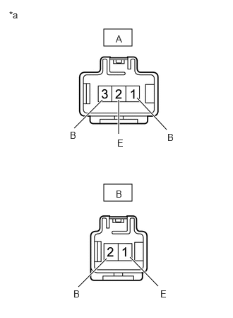
| *a | Component without harness connected
(Quick Heater Assembly) |
Measure the resistance according to the value(s) in the table below.
- Standard Resistance:
Tester Connection Condition Specified Condition A-1 (B) - A-2 (E) Always Below 10 kΩ A-3 (B) - A-2 (E) Always Below 10 kΩ A-3 (B) - B-1 (E) Always Below 10 kΩ B-2 (B) - B-1 (E) Always Below 10 kΩ
- Result:
Result Proceed to OK (except G16E-GTS) A OK (for G16E-GTS) B NG C
A
Click hereVehicle Interior>HEATING / AIR CONDITIONING>AIR CONDITIONING AMPLIFIER (except G16E-GTS)>REMOVAL
B
Click hereVehicle Interior>HEATING / AIR CONDITIONING>AIR CONDITIONING AMPLIFIER (for G16E-GTS)>REMOVAL
C
Disconnect the A88 No. 2 semiconductor power integration ECU connector.
Measure the resistance according to the value(s) in the table below.
- Standard Resistance:
Tester Connection Condition Specified Condition J1-1 (B) - A88-1 (L) Always Below 1 Ω J1-3 (B) - A88-2 (L) Always Below 1 Ω J2-2 (B) - A88-16 (L) Always Below 1 Ω J1-1 (B) or A88-1 (L) - Other terminals and body ground Always 10 kΩ or higher J1-3 (B) or A88-2 (L) - Other terminals and body ground Always 10 kΩ or higher J2-2 (B) or A88-16 (L) - Other terminals and body ground Always 10 kΩ or higher
- Result:
Proceed to OK NG
OK
NG
Read the Data List according to the display on the GTS.
- Body Electrical > Power Integration No.2 > Data List
-
Tester Display Measurement Item Range Normal Condition Diagnostic Note PTC Heater No.1 Fuse Shut Off Status Quick heater assembly (PTC1) fuse condition OFF or ON OFF: Fuse shut off
ON: Fuse not shut off- PTC Heater No.2 Fuse Shut Off Status Quick heater assembly (PTC2) fuse condition OFF or ON OFF: Fuse shut off
ON: Fuse not shut off- PTC Heater No.3 Fuse Shut Off Status Quick heater assembly (PTC3) fuse condition OFF or ON OFF: Fuse shut off
ON: Fuse not shut off-
- Body Electrical > Power Integration No.2 > Data List
-
Tester Display PTC Heater No.1 Fuse Shut Off Status PTC Heater No.2 Fuse Shut Off Status PTC Heater No.3 Fuse Shut Off Status - 50003 474 783,788,793
- OK:
The Data List value displays "OFF".
- Result:
Proceed to OK NG
OK
NG