G16E-GTS FUEL FUEL PRESSURE SENSOR(for High Pressure) INSTALLATION
CAUTION / NOTICE / HINT
- NOTICE:
-
This procedure includes the installation of small-head bolts. Refer to Small-Head Bolts of Basic Repair Hint to identify the small-head bolts.
-
Click hereGeneral>INTRODUCTION>REPAIR INSTRUCTION>PRECAUTION
PROCEDURE

 89458
1.INSTALL FUEL PRESSURE SENSOR
- HINT:
-
Perform "Inspection After Repair" after replacing the fuel pressure sensor.
-
Click hereEngine / Hybrid System>G16E-GTS (ENGINE CONTROL)>SFI SYSTEM>INITIALIZATION
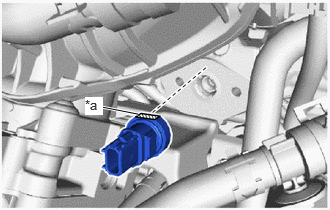
| *a | Cutout (Fuel Pressure Sensor) |
Temporarily install the fuel pressure sensor to the fuel delivery pipe as shown in the illustration.
- NOTICE:
-
Make sure that the cutout of the fuel pressure sensor are facing upward.
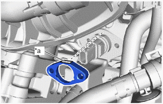
| *a | Cutout (No. 1 Fuel Pressure Sensor Holder) |
Temporarily install the No. 1 fuel pressure sensor holder to the fuel delivery pipe as shown in the illustration.
- NOTICE:
-
Make sure that the cutout of the fuel pressure sensor holder are facing upward.
Using an 8 mm socket wrench, install the 2 bolts.
- Torque:
- 10 N*m (102 kgf*cm, 7 ft.*lbf)
Connect the fuel pressure sensor connector.
12601B
2.INSTALL NO. 1 ENGINE COVER SUB-ASSEMBLY
3.CONNECT CABLE TO NEGATIVE AUXILIARY BATTERY TERMINAL
4. INITIALIZATION AFTER RECONNECTING BATTERY TERMINAL
Click hereGeneral>SETUP>WHEN DISCONNECTING OR RECONNECTING BATTERY TERMINAL>WORK PROCEDURE
- HINT:
-
When disconnecting and reconnecting the battery, there is an automatic learning function that completes learning when the respective system is used.
-
Click hereGeneral>SETUP>WHEN DISCONNECTING OR RECONNECTING BATTERY TERMINAL>AUTOMATIC LEARNING CHART
5.INSPECT FOR FUEL LEAK
6.PERFORM INITIALIZATION
Perform "Inspection After Repair" after replacing the fuel pressure sensor.
Click hereEngine / Hybrid System>G16E-GTS (ENGINE CONTROL)>SFI SYSTEM>INITIALIZATION