G16E-GTS INTAKE / EXHAUST INTAKE MANIFOLD INSTALLATION
PROCEDURE

 17172
1.INSTALL MANIFOLD TO CYLINDER HEAD GASKET
Install a new No. 1 intake manifold to head gasket to the intake manifold.
22030
2.INSTALL THROTTLE WITH THROTTLE POSITION SENSOR BODY ASSEMBLY
Install the new gaskets to throttle with throttle position sensor body assembly.
Install the throttle with throttle position sensor body assembly to intake manifold.
17360A
3.INSTALL AIR TUBE ASSEMBLY
Install the new gaskets to air tube assembly.
Install the ir tube assembly to the intake manifold with the 4 bolts.
- Torque:
- 10 N*m (102 kgf*cm, 7 ft.*lbf)
23826
4.INSTALL NO. 1 FUEL VAPOR FEED HOSE
Engage the 2 clamps to install the air tube assembly to the intake manifold.
17177
5.INSTALL NO. 1 INTAKE MANIFOLD TO HEAD GASKET
Install the new gaskets to the cylinder head sub-assembly.
12218
6.INSTALL NO. 1 VENTILATION FLANGE SEPARATOR
Install the No. 1 ventilation flange separator to the cylinder head sub-assembly.
17111
7.INSTALL INTAKE MANIFOLD
Install the No. 5 air hose to the air tube and tighten the hose clamp.
- Torque:
- 3.0 N*m (31 kgf*cm, 27 in.*lbf)
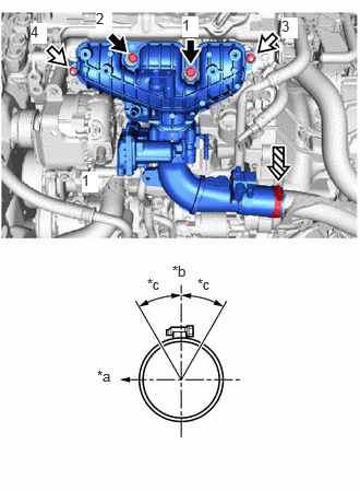
| *a | Rear of Vehicle |
| *b | Top of Vehicle |
| *c | 30° |

|
Bolt |

|
Nut |

|
Clamp |
Tighten the 2 bolts and 2 nuts in the order shown in the illustration.
- Torque:
- 21 N*m (214 kgf*cm, 15 ft.*lbf)
17872
8.INSTALL INTAKE AIR CONNECTOR BRACKET
Install the intake air connector bracket to the intake manifold with the 2 bolts.
- Torque:
- 21 N*m (214 kgf*cm, 15 ft.*lbf)
16261
9.INSTALL WATER BY-PASS HOSE
Connect the No. 2 water by-pass hose and No. 3 water by-pass hose to the throttle body with motor assembly and slide the 2 clips to secure them.
82121
10.CONNECT ENGINE WIRE
Install the clamp.
Install the bolt.
- Torque:
- 10 N*m (102 kgf*cm, 7 ft.*lbf)
Connect the connector.
89421K
11.INSTALL NO. 1 TURBO PRESSURE SENSOR
Install the No. 1 turbo pressure sensor to the intake manifold with the bolt.
- Torque:
- 10 N*m (102 kgf*cm, 7 ft.*lbf)
12.INSTALL WIRE HARNESS CLAMP BRACKET
Install the wire harness clamp bracket to the intake manifold with the 2 bolts.
- Torque:
- 10 N*m (102 kgf*cm, 7 ft.*lbf)
23826
13.CONNECT NO. 1 FUEL VAPOR FEED HOSE
Connect the No. 1 fuel vapor feed hose to the vacuum switching valve assembly.
82121
14.INSTALL ENGINE WIRE
Engage the 3 clamps to install the engine wire to the intake manifold.
16288
15.INSTALL NO. 4 WATER BY-PASS PIPE
Install the No. 4 water by-pass pipe to the intake manifold with the 3 bolts.
- Torque:
- 10 N*m (102 kgf*cm, 7 ft.*lbf)
Connect the No. 7 water by-pass hose, No. 2 water by-pass hose, No. 1 water by-pass hose and slide the 3 clips to secure them.
82121
16.INSTALL ENGINE WIRE
Install the engine wire to the engine assembly with the bolt and nut.
- Torque:
- Bolt : 10 N*m (102 kgf*cm, 7 ft.*lbf)
- Nut : 9.8 N*m (100 kgf*cm, 87 in.*lbf)
Engage the 2 clamps and connect the 5 connectors to install the engine wire.
17.ADD ENGINE COOLANT
51410
18.INSTALL NO. 1 ENGINE UNDER COVER ASSEMBLY