G16E-GTS INTAKE / EXHAUST INTAKE MANIFOLD REMOVAL
CAUTION / NOTICE / HINT
The necessary procedures (adjustment, calibration, initialization or registration) that must be performed after parts are removed and installed, or replaced during intake manifold removal/installation are shown below.
| Replaced Part or Performed Procedure | Necessary Procedure | Effect/Inoperative Function when Necessary Procedure not Performed | Link |
|---|---|---|---|
| Cleaning the deposits from the throttle body with motor assembly | Inspection After Repair | ·
Poor idle, etc. ·
Engine start function, etc. |
( ) |
PROCEDURE

 51410
1.REMOVE NO. 1 ENGINE UNDER COVER ASSEMBLY
2.DRAIN ENGINE COOLANT
82121
3.SEPARATE ENGINE WIRE
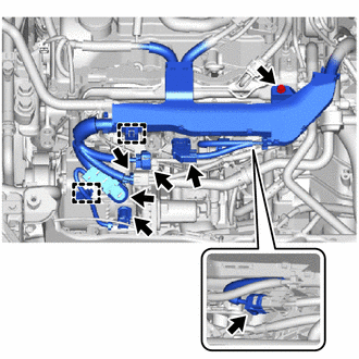
Disconnect the 5 connectors and disengage the 2 clamps.
Remove the bolt, nut and separate the engine wire from the engine assembly.
16288
4.REMOVE NO. 4 WATER BY-PASS PIPE
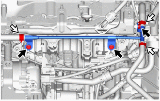

|
Bolt |

|
Clamp |
Slide the 3 clips and disconnect the No. 7 water by-pass hose, No. 2 water by-pass hose and No. 1 water by-pass hose.
Remove the 3 bolts and No. 4 water by-pass pipe from the intake manifold.
82121
5.SEPARATE ENGINE WIRE
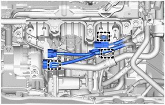
Disengage the 3 clamps to disconnect the engine wire from the intake manifold.
23826
6.SEPARATE NO. 1 FUEL VAPOR FEED HOSE
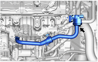
Separate the No. 1 fuel vapor feed hose assembly from the vacuum switching valve assembly.
7.REMOVE WIRE HARNESS CLAMP BRACKET
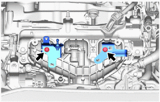
Remove the 2 bolts and 2 brackets from the intake manifold.
89421K
8.REMOVE NO. 1 REMOVE TURBO PRESSURE SENSOR
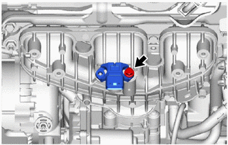
Remove the bolt and No. 1 turbo pressure sensor from the intake manifold.
82121
9.REMOVE ENGINE WIRE
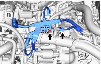
Disconnect the connector.
Remove the bolt.
Disengage the clamp to disconnect the engine wire from the intake manifold.
16261
10.REMOVE WATER BY-PASS HOSE
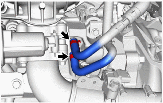
Slide the 2 clips and disconnect the No. 2 water by-pass hose and No. 3 water by-pass hose to from the throttle body with motor assembly.
17872
11.REMOVE INTAKE AIR CONNECTOR BRACKET
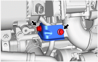
Remove the 2 bolts and intake air connector bracket from the intake manifold.
17111
12.REMOVE INTAKE MANIFOLD
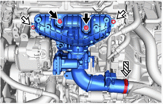
|
|
Bolt |
|
|
Nut |

|
Clamp |
Loosen the hose clamp.
Remove the 2 bolts, 2 nuts and intake manifold from the No. 1 ventilation flange separator.
12218
13.REMOVE NO. 1 VENTILATION FLANGE SEPARATOR
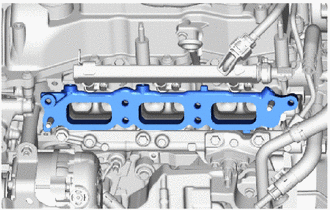
Remove the No. 1 ventilation flange separator from the cylinder head sub-assembly.
17177
14.REMOVE NO. 1 INTAKE MANIFOLD TO HEAD GASKET
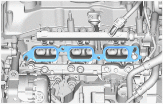
Remove the No.1 intake manifold to head gasket from the cylinder head sub-assembly.
23826
15.REMOVE NO. 1 FUEL VAPOR FEED HOSE
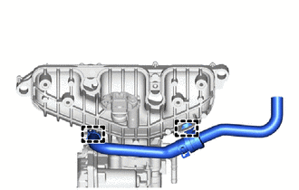
Disengage 2 clamps and remove the No. 1 fuel vapor feed hose.
17360A
16.REMOVE AIR TUBE ASSEMBLY
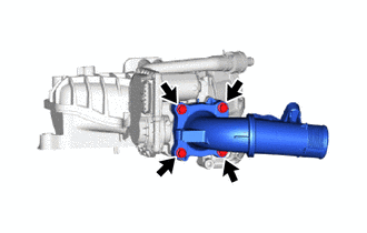
Remove the 2 bolts and air tube assembly.
22030
17.REMOVE THROTTLE WITH THROTTLE POSITION SENSOR BODY ASSEMBLY
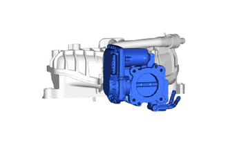
Remove the throttle with throttle position sensor body assembly.
17172
18.REMOVE MANIFOLD TO CYLINDER HEAD GASKET
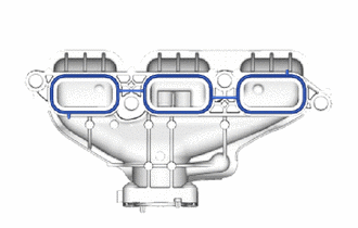
Remove the manifold to cylinder head gasket from the intake manifold.