GF1A TRANSFER / 4WD / AWD ACTIVE TORQUE SPLIT AWD SYSTEM 4WD Control Switch Circuit
DESCRIPTION
Operate the 4WD control switch (No. 2 combination switch assembly) and check that the Data List display and the messages in the multi-information display change according to the switch operation.
WIRING DIAGRAM
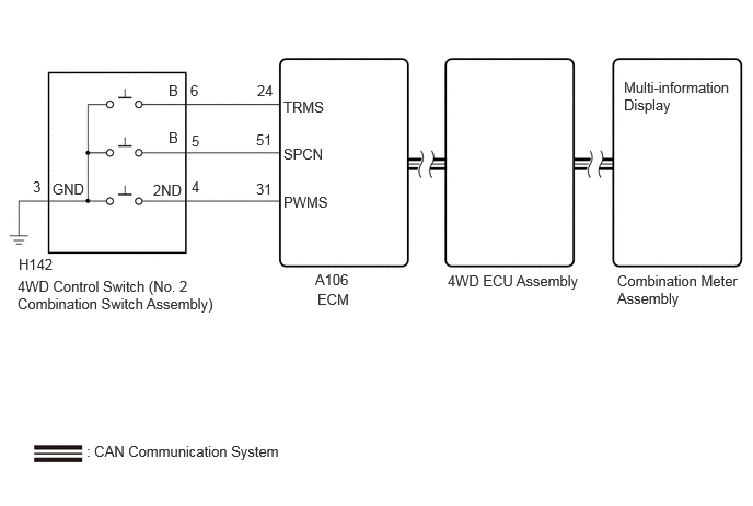
CAUTION / NOTICE / HINT
- NOTICE:
-
Before replacing the ECM, refer to Service Bulletin.
PROCEDURE
Using the GTS, check for DTCs.
Click herePower Source / Network>NETWORKING>CAN COMMUNICATION SYSTEM (for Gasoline Model)>DIAGNOSIS SYSTEM
Check that DTCs indicating a CAN communication system malfunction are not output.
- Result:
Result Proceed to DTCs are not output. A DTCs are output. B
A
B
According to the display on the GTS, read the Data List.
- Powertrain > Engine > Data List
-
Tester Display Measurement Item Range Normal Condition Diagnostic Note Drive Mode Status Drive Mode Status Normal / Power / Sport / Sport / Sport+ / Comfort / ECO / Track - -
- Powertrain > Engine > Data List
-
Tester Display Drive Mode Status - 50003 372 2
Operate the 4WD control switch (No. 2 combination switch assembly) and check that the Data List display and the messages in the multi-information display change according to the switch operation.
- OK:
4WD Control Switch (No. 2 Combination Switch Assembly) Operation Data List Display Multi-information Display Message PUSH NORMAL Normal NORMAL SPORT Sport SPORT TRACK Track TRACK
- Result:
Result Proceed to When the switch is operated, the Data List display and message do not change A When the switch is operated, the Data List display changes, but the message does not change B When the switch is operated, the Data List display and indicator change normally C
A
B
Click hereVehicle Interior>METER / GAUGE / DISPLAY>METER / GAUGE SYSTEM>HOW TO PROCEED WITH TROUBLESHOOTING
C
Click hereGeneral>INTRODUCTION>HOW TO TROUBLESHOOT ECU CONTROLLED SYSTEMS>HOW TO PROCEED WITH TROUBLESHOOTING
Inspect the 4WD control switch (No. 2 combination switch assembly).
Click hereDrivetrain>GF1A (TRANSFER / 4WD / AWD)>4WD CONTROL SWITCH>INSPECTION
- Result:
Proceed to OK NG
OK
NG
Turn the ignition switch off.
Disconnect the A106 ECM connector.
Disconnect the H142 4WD control switch (No. 2 combination switch assembly) connector.
Measure the resistance according to the value(s) in the table below.
- Standard Resistance:
Tester Connection Condition Specified Condition A106-24 (TRMS) - H142-6 (B) Always Below 1 Ω A106-31 (PWMS) - H142-4 (2ND) Always Below 1 Ω A106-51 (SPCN) - H142-5 (B) Always Below 1 Ω H142-3 (GND) - Body ground Always Below 1 Ω A106-24 (TRMS) or H142-6 (B) - Body ground Always 10 kΩ or higher A106-31 (PWMS) or H142-4 (2ND) - Body ground Always 10 kΩ or higher A106-24 (TRMS) or H142-6 (B) - A106-31 (PWMS) or H142-4 (2ND) Always 10 kΩ or higher
- Result:
Proceed to OK NG
OK
NG