TELEMATICS TELEMATICS SYSTEM(for eCall) B1AC07F Speaker Cable Connection Actuator Stuck Off
DESCRIPTION
If there is an open in a speaker circuit, the telephone transceiver assembly detects it and stops output to the speakers.
Thus sound cannot be heard from the speakers even if there is no malfunction in the telephone transceiver assembly or front No. 3 speaker assembly.
| DTC No. | Detection Item | DTC Detection Condition | Trouble Area |
|---|---|---|---|
| B1AC07F | Speaker Cable Connection Actuator Stuck Off | The malfunction is detected in the telephone speaker circuit for approximately 10 seconds or more. | ·
Front No. 3 speaker assembly ·
Telephone transceiver assembly ·
Harness or connector |
WIRING DIAGRAM
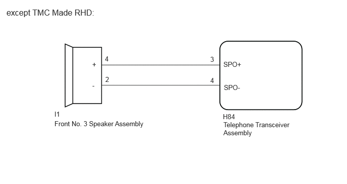
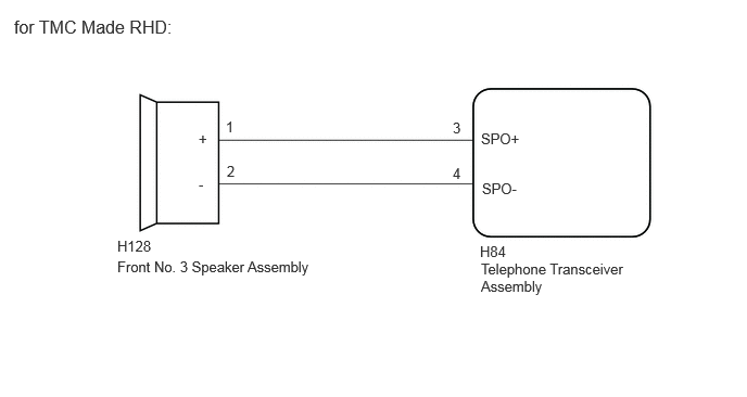
CAUTION / NOTICE / HINT
- NOTICE:
-
When replacing the telephone transceiver assembly, make sure to replace it with a new one.
PROCEDURE
Clear the DTCs.
- Body Electrical > Telematics > Clear DTCs
- 50002 459
- Result:
Proceed to NEXT
NEXT
Turn the ignition switch to ON and wait for 10 seconds or more.
Check for DTCs and check that no DTCs are output.
- Body Electrical > Telematics > Trouble Codes
- 50001 459
- Result:
Result Proceed to DTCs are not output A DTC B1AC07F is output B
A
Click hereGeneral>INTRODUCTION>HOW TO TROUBLESHOOT ECU CONTROLLED SYSTEMS>HOW TO PROCEED WITH TROUBLESHOOTING
B
Check the vehicle specification.
- Result:
Result Proceed to except TMC Made RHD A for TMC Made RHD B
A
B
Disconnect the I1 front No. 3 speaker assembly connector.
Disconnect the H84 telephone transceiver assembly connector.
Measure the resistance according to the value (s) in the table below.
- Standard Resistance:
Tester Connection Condition Specified Condition I1-4 (+) - H84-3 (SPO+) Always Below 1 Ω I1-2 (-) - H84-4 (SPO-) Always Below 1 Ω I1-4 (+) or H84-3 (SPO+) - Body ground Always 10 kΩ or higher I1-2 (-) or H84-4 (SPO-) - Body ground Always 10 kΩ or higher
- Result:
Proceed to OK NG
OK
NG
Replace the No. 3 front speaker assembly.
- Result:
Proceed to NEXT
NEXT
Clear the DTCs.
- Body Electrical > Telematics > Clear DTCs
- 50002 459
- Result:
Proceed to NEXT
NEXT
Turn the ignition switch to ON and wait for 10 seconds or more.
Check for DTCs and check that no DTCs are output.
- Body Electrical > Telematics > Trouble Codes
- 50001 459
- Result:
Result Proceed to DTCs are not output A DTC B1AC07F is output B
A
B
Replace the telephone transceiver assembly with a new one.
- Result:
Proceed to NEXT
NEXT
Disconnect the H128 front No. 3 speaker assembly connector.
Disconnect the H84 telephone transceiver assembly connector.
Measure the resistance according to the value (s) in the table below.
- Standard Resistance:
Tester Connection Condition Specified Condition H128-1 (+) - H84-3 (SPO+) Always Below 1 Ω H128-2 (-) - H84-4 (SPO-) Always Below 1 Ω H128-1 (+) or H84-3 (SPO+) - Body ground Always 10 kΩ or higher H128-2 (-) or H84-4 (SPO-) - Body ground Always 10 kΩ or higher
- Result:
Proceed to OK NG
OK
NG
Replace the No. 3 front speaker assembly.
- Result:
Proceed to NEXT
NEXT
Clear the DTCs.
- Body Electrical > Telematics > Clear DTCs
- 50002 459
- Result:
Proceed to NEXT
NEXT
Turn the ignition switch to ON and wait for 10 seconds or more.
Check for DTCs and check that no DTCs are output.
- Body Electrical > Telematics > Trouble Codes
- 50001 459
- Result:
Result Proceed to DTCs are not output A DTC B1AC07F is output B
A
B
Replace the telephone transceiver assembly with a new one.
- Result:
Proceed to NEXT
NEXT