SUPPLEMENTAL RESTRAINT SYSTEMS SIDE AIRBAG SENSOR(for 5 Door Center Pillar) INSTALLATION
CAUTION / NOTICE / HINT
- HINT:
- ·
Use the same procedure for the RH and LH sides.
·The procedure listed below is for the LH side.
PROCEDURE

 89831
1.INSTALL NO. 1 SIDE AIRBAG SENSOR
Check that the ignition switch is off.
Check that the cable is disconnected from the negative (-) auxiliary battery terminal.
- CAUTION:
- ·
Wait at least 90 seconds after disconnecting the cable from the negative (-) auxiliary battery terminal to disable the SRS system.
·If the airbag deploys for any reason, it may cause a serious accident.
Engage the claw to hold the No. 1 side airbag sensor.
Install the No. 1 side airbag sensor with the nut.
- Torque:
- 7.8 N*m (80 kgf*cm, 69 in.*lbf)
- NOTICE:
- ·
If the No. 1 side airbag sensor has been dropped, replace it with a new one.
·When installing the No. 1 side airbag sensor, be careful that the SRS wiring does not interfere with or is not pinched between other parts.
·Tighten the bolt while holding the No. 1 side airbag sensor because the No. 1 side airbag sensor guide is easily damaged.
Check that there is no looseness in the installation parts of the No. 1 side airbag sensor.
Connect the airbag connector.
- NOTICE:
-
When connecting any airbag connector, take care not to damage the airbag wire harness.
- HINT:
-
Refer to How to Connect or Disconnect Airbag Connector: Click hereVehicle Interior>SUPPLEMENTAL RESTRAINT SYSTEMS>AIRBAG SYSTEM>HOW TO CONNECT OR DISCONNECT AIRBAG CONNECTOR
73210
2.CONNECT FRONT SEAT OUTER BELT ASSEMBLY
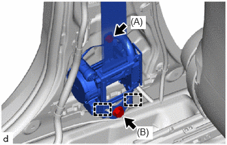
Engage the guides to connect the front seat outer belt assembly.
Temporarily install the 2 bolts.
Tighten the bolt (A) and then bolt (B).
- Torque:
- Bolt (A) : 12.5 N*m (127 kgf*cm, 9 ft.*lbf)
- Bolt (B) : 42 N*m (428 kgf*cm, 31 ft.*lbf)
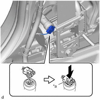
| *a | Locking Button |
Connect the pretensioner connector and lock the locking button as shown in the illustration.
- NOTICE:
-
Securely lock the locking button.
62413A
3.INSTALL CENTER PILLAR LOWER GARNISH
4.CONNECT CABLE TO NEGATIVE AUXILIARY BATTERY TERMINAL
for M15A-FKS:
Click hereGeneral>MAINTENANCE>M15A-FKS AUXILIARY BATTERY>INSTALLATION
for M15A-FXE:
Click hereGeneral>MAINTENANCE>M15A-FXE AUXILIARY BATTERY>INSTALLATION
for 1KR-FE:
Click hereGeneral>MAINTENANCE>1KR-FE AUXILIARY BATTERY>INSTALLATION
5. INITIALIZATION AFTER RECONNECTING AUXILIARY BATTERY TERMINAL
Click hereGeneral>SETUP>WHEN DISCONNECTING OR RECONNECTING BATTERY TERMINAL>WORK PROCEDURE
- HINT:
-
When disconnecting and reconnecting the auxiliary battery, there is an automatic learning function that completes learning when the respective system is used.
-
Click hereGeneral>SETUP>WHEN DISCONNECTING OR RECONNECTING BATTERY TERMINAL>AUTOMATIC LEARNING CHART
6. PERFORM DIAGNOSTIC SYSTEM CHECK
7.CHECK SRS WARNING LIGHT