RM36W0E
_56
Audio / Visual / Telematics
_091907
TELEMATICS
_0476471
TELEMATICS SYSTEM(for TAS Type)
J
TELEMATICS TELEMATICS SYSTEM(for TAS Type) Telematics Service cannot be Used
DESCRIPTION
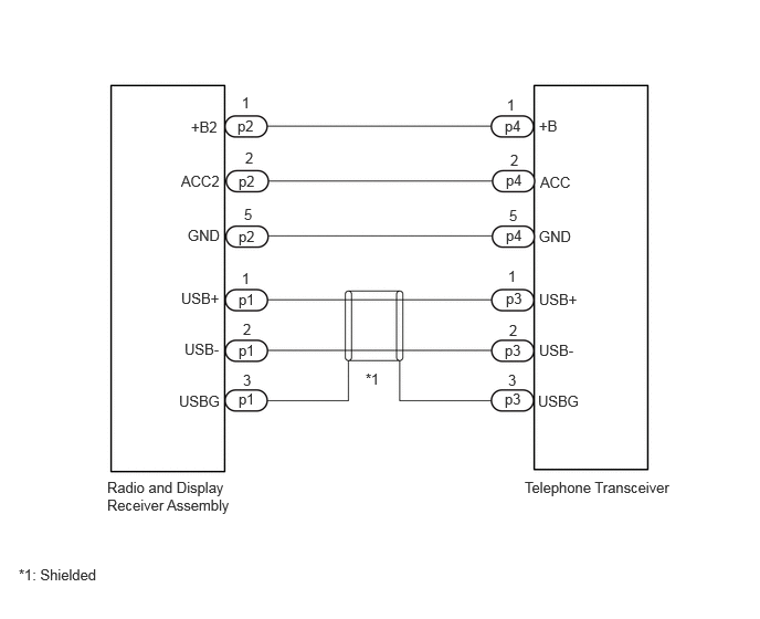
This is the power source and USB circuit to operate the telephone transceiver.
WIRING DIAGRAM
4.948,4.51 6.406,4.906
1.458,0.396
10
false
Telephone Transceiver
1.01,4.51 2.219,4.854
1.208,0.344
10
false
Radio and Display Receiver Assembly
0.177,5.333 0.969,5.542
0.792,0.208
10
false
*1: Shielded
3.448,3.49 3.719,3.708
0.271,0.219
10
false
*1
1.802,1.115 2.167,1.333
0.365,0.219
10
false
+B2
5.083,1.104 5.563,1.313
0.479,0.208
10
false
+B
1.708,1.625 2.271,1.833
0.563,0.208
10
false
ACC2
5.094,1.635 5.656,1.844
0.563,0.208
10
false
ACC
1.771,2.135 2.281,2.344
0.51,0.208
10
false
GND
5.083,2.146 5.594,2.354
0.51,0.208
10
false
GND
1.708,2.729 2.219,2.938
0.51,0.208
10
false
USB+
5.083,2.74 5.594,2.948
0.51,0.208
10
false
USB+
1.74,3.208 2.25,3.417
0.51,0.208
10
false
USB-
5.083,3.219 5.594,3.427
0.51,0.208
10
false
USB-
1.688,3.698 2.198,3.906
0.51,0.208
10
false
USBG
5.073,3.698 5.583,3.906
0.51,0.208
10
false
USBG
4.792,2.521 5.052,2.729
0.26,0.208
10
false
1
2.281,2.542 2.542,2.75
0.26,0.208
10
false
1
2.292,3.021 2.552,3.229
0.26,0.208
10
false
2
4.802,3.031 5.063,3.24
0.26,0.208
10
false
2
4.792,3.5 5.052,3.802
0.26,0.302
10
false
3
2.292,3.5 2.521,3.677
0.229,0.177
10
false
3
4.771,2.729 5.281,2.938
0.51,0.208
10
false
p3
4.76,3.219 5.271,3.427
0.51,0.208
10
false
p3
4.76,3.677 5.271,3.885
0.51,0.208
10
false
p3
2.25,3.677 2.76,3.885
0.51,0.208
10
false
p1
2.25,3.219 2.76,3.427
0.51,0.208
10
false
p1
2.25,2.74 2.76,2.948
0.51,0.208
10
false
p1
2.281,0.885 2.542,1.094
0.26,0.208
10
false
1
4.781,0.906 5.042,1.115
0.26,0.208
10
false
1
4.813,1.427 5.073,1.635
0.26,0.208
10
false
2
2.313,1.406 2.531,1.594
0.219,0.188
10
false
2
2.302,1.938 2.563,2.146
0.26,0.208
10
false
5
4.802,1.948 5.063,2.156
0.26,0.208
10
false
5
4.76,1.104 5.271,1.313
0.51,0.208
10
false
p4
4.771,1.615 5.281,1.823
0.51,0.208
10
false
p4
4.771,2.135 5.281,2.344
0.51,0.208
10
false
p4
2.25,2.146 2.625,2.354
0.375,0.208
10
false
p2
2.25,1.625 2.594,1.833
0.344,0.208
10
false
p2
2.24,1.104 2.583,1.313
0.344,0.208
10
false
p2
PROCEDURE
1.CHECK HARNESS AND CONNECTOR (TELEPFONE TRANSCEIVER - RADIO AND DISPLAY RECEIVER ASSEMBLY)
a.
Disconnect the p3 and p4 telephone transceiver connector.
b.
Disconnect the p1 and p2 radio and display receiver assembly connector.
c.
Measure the resistance according to the value(s) in the table below.
- Standard Resistance:
Tester Connection Condition Specified Condition p4-1 (+B) - p2-1 (+B2) Always Below 1 Ω p4-2 (ACC) - p2-2 (ACC2) Always Below 1 Ω p4-5 (GND) - p2-5 (GND) Always Below 1 Ω p3-1 (USB+) - p1-1 (USB+) Always Below 1 Ω p3-2 (USB-) - p1-2 (USB-) Always Below 1 Ω p3-3 (USBG) - p1-3 (USBG) Always Below 1 Ω p4-5 (GND) or p2-5 (GND) - Body ground Always 10 kΩ or higher p3-3 (USBG) or p1-3 (USBG) - Body ground Always 10 kΩ or higher
- Result:
Proceed to OK NG
OK
2.CHECK HARNESS AND CONNECTOR (RADIO AND DISPLAY RECEIVER ASSEMBLY POWER SOURCE)
NG
REPAIR OR REPLACE HARNESS OR CONNECTOR
2.CHECK HARNESS AND CONNECTOR (RADIO AND DISPLAY RECEIVER ASSEMBLY POWER SOURCE)
a.
Disconnect the telephone transceiver connector.
b.
1.479,0.208 1.948,0.438
0.469,0.229
0.708,1.771 1.354,1.323
true
2.479,1.865 1.917,1.344
true
2.719,0.792 2.115,1.229
true
1.646,0.25 2.104,0.448
0.458,0.198
10
false
p4
0.135,0.125 0.448,0.323
0.313,0.198
10
false
*a
2.792,0.698 3.104,0.896
0.313,0.198
10
false
+B
2.573,1.802 3.177,2
0.604,0.198
10
false
ACC
0.375,1.719 0.729,1.917
0.354,0.198
10
false
GND
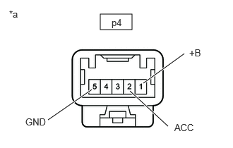
| *a | Front view of wire harness connector
(to Telephone Transceiver) |
Measure the resistance according to the value(s) in the table below.
- Standard Resistance:
Tester Connection Condition Specified Condition p4-5 (GND) - Body ground Always Below 1 Ω
c.
Measure the voltage according to the value(s) in the table below.
- Standard Voltage:
Tester Connection Switch Condition Specified Condition p4-1 (+B) - p4-5 (GND) Ignition switch off 11 to 14 V p4-2 (ACC) - p4-5 (GND) Ignition switch ACC 11 to 14 V
- Result:
Proceed to OK NG
OK
REPLACE TELEPHONE TRANSCEIVER
NG
REPLACE RADIO AND DISPLAY RECEIVER ASSEMBLY