REAR SUSPENSION REAR AXLE BEAM REMOVAL
CAUTION / NOTICE / HINT
The necessary procedures (adjustment, calibration, initialization, or registration) that must be performed after parts are removed and installed, or replaced during the front axle hub sub-assembly removal/installation are shown below.
| Replacement Part or Procedure | Necessary Procedures | Effect/Inoperative Function When Necessary Procedures are not Performed | Link |
|---|---|---|---|
| for HV Model TMC Made:
Auxiliary battery terminal is disconnected/reconnected |
Memorize steering angle neutral point | Parking assist monitor system | ( ) |
| Rear wheel alignment adjustment | for HV Model:
1.
Perform "Reset Memory" 2.
Perform calibration (linear solenoid valve offset learning, SM solenoid valve offset learning, brake pedal stroke sensor assembly zero point calibration, system information memorization, and yaw rate and acceleration sensor zero point calibration) |
·
DTCs are stored ·
ABS warning light illuminates ·
Brake system warning light (yellow indicator) ·
Slip indicator light illuminates ·
VSC disabled or malfunctions |
for TMC Made:
( )
for TMMF, TMMCZ Made: ( )
|
| for Gasoline Model:
Calibration |
·
DTCs are stored ·
ABS warning light illuminates ·
Slip indicator light illuminates ·
VSC disabled or malfunctions |
for TMC Made:
( )
for TMMF, TMMCZ Made: ( )
|
|
| Suspension, tires, etc.
(The vehicle height changes because of suspension or tire replacement.) |
·
Ultrasonic sensor detection angle ·
Ultrasonic sensor detection angle registration |
Parking support brake system | ()
|
| Rear television camera assembly optical axis (Back camera position setting) | Parking assist monitor system | ()
|
- HINT:
-
When the cable is disconnected/reconnected to the auxiliary battery terminal, systems temporarily stop operating. However, each system has a function that completes learning the first time the system is used.
- for TMC Made HV Model:·
Learning completes when vehicle is driven
Effect/Inoperative Function When Necessary Procedures are not Performed Necessary Procedures Link Lane tracing assist system Drive the vehicle straight ahead at 35 km/h (22 mph) or more for 5 seconds or more. ( )
Pre-collision system
·Learning completes when vehicle is operated normally
Effect/Inoperative Function When Necessary Procedures are not Performed Necessary Procedures Link Power door lock control system
·Back door opener
Perform door unlock operation with door control switch or electrical key transmitter sub-assembly switch. ( )
Air conditioning system After the ignition switch is turned to ON, the servo motor standard position is recognized. -
PROCEDURE

 42450B
1.REMOVE REAR AXLE HUB AND BEARING ASSEMBLY LH (for TMC Made)
42450A
2.REMOVE REAR AXLE HUB AND BEARING ASSEMBLY RH (for TMC Made)
- HINT:
-
Perform the same procedure as for the LH side.
42450B
3.REMOVE REAR AXLE HUB AND BEARING ASSEMBLY LH (for TMMF, TMMCZ Made)
42450A
4.REMOVE REAR AXLE HUB AND BEARING ASSEMBLY RH (for TMMF, TMMCZ Made)
- HINT:
-
Perform the same procedure as for the LH side.
48231B
5.REMOVE REAR COIL SPRING LH (for TMC Made)
48231A
6.REMOVE REAR COIL SPRING RH (for TMC Made)
- HINT:
-
Perform the same procedure as for the LH side.
48231B
7.REMOVE REAR COIL SPRING LH (for TMMF, TMMCZ Made)
48231A
8.REMOVE REAR COIL SPRING RH (for TMMF, TMMCZ Made)
- HINT:
-
Perform the same procedure as for the LH side.
42110F
9.INSTALL REAR AXLE BEAM ASSEMBLY
Support the rear axle beam assembly using an engine lifter, 2 wooden blocks and 2 plate lift attachments or equivalent tools.
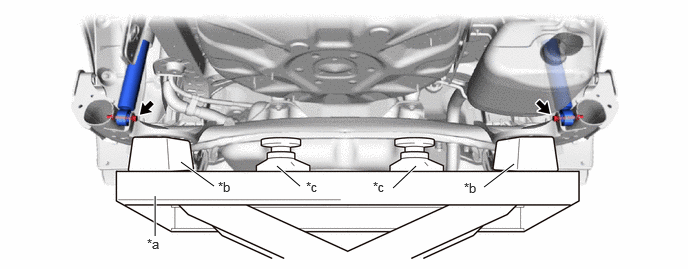
| *a | Engine Lifter | *b | Wooden Block |
| *c | Plate Lift Attachment | - | - |
- CAUTION:
-
Make sure to secure the rear axle beam assembly to prevent it from dropping.
Remove the 2 bolts while holding the 2 nuts and separate the rear axle beam assembly from the rear shock absorber assemblies LH and RH.
- NOTICE:
-
Because the nuts have their own stoppers, do not turn the nuts. Loosen the bolts with the nuts secured.
Remove the 2 bolts and rear axle beam assembly from the vehicle.
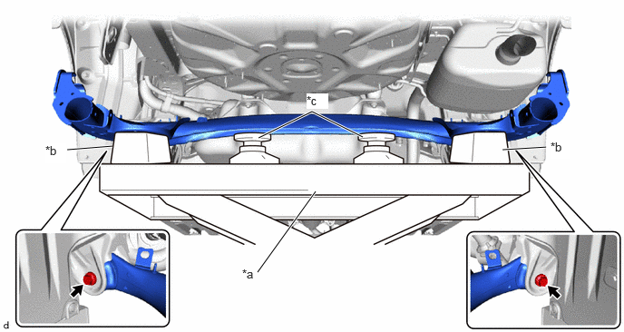
| *a | Engine Lifter | *b | Wooden Block |
| *c | Plate Lift Attachment | - | - |