Removal / installation · Vehicles built Aug 2005 – Dec 2005
Versions by build date: Aug 2005 – Dec 2005from Jan 2006
NOTICE:
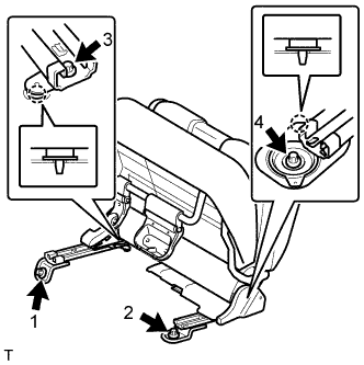
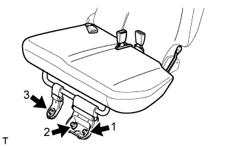
Always use "Torx" socket wrench E10 when installing the rear seat.
1.
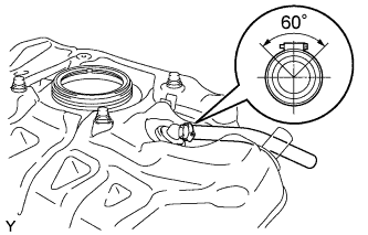
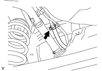
CONNECT FUEL TANK BREATHER TUBE
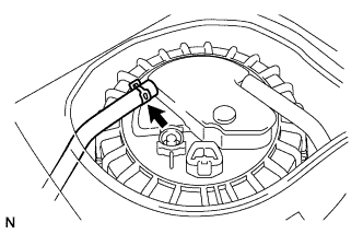
Connect the fuel tank breather tube with the clamp.
Tighten the clamp bolt.
2.
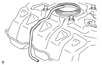
INSTALL FUEL EMISSION TUBE NO.2
Install fuel emission tube No. 2 onto the fuel tank.
3.
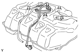
INSTALL FUEL TANK MAIN TUBE SUB-ASSEMBLY
Install the fuel tank main tube onto the fuel tank.
4.
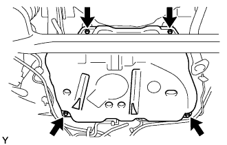
INSTALL FUEL TANK ASSEMBLY
Clean the bolt hole and remove any grease.
Install the fuel tank with 4 new bolts.
Torque:
14 N*m{
146 kgf*cm
, 10 ft.*lbf
}
5.
CONNECT FUEL EMISSION TUBE NO. 2
Connect fuel emission tube No. 2 with the clamp.
6.
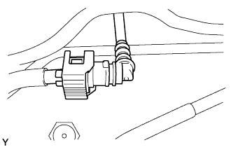
CONNECT FUEL TANK MAIN TUBE SUB-ASSEMBLY
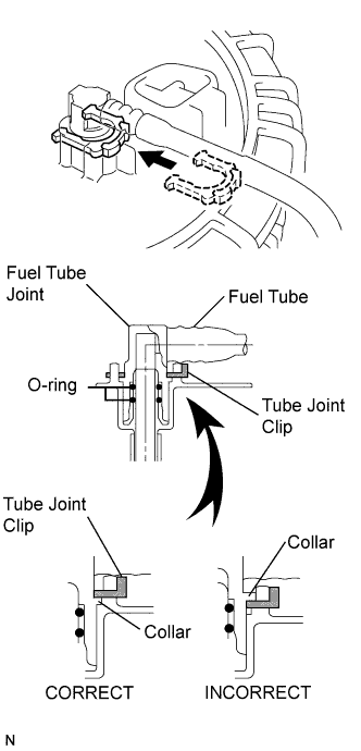
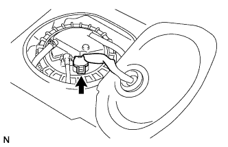
Align the fuel tube connector with the pipe, push the fuel tube connector in until the retainer makes a click sound, then lock the cover of the connector.
NOTICE:
Check that there are no scratches or foreign matter on the disconnected parts of the fuel tube connector and pipe before performing this work.
After connecting, pull the pipe and fuel tube connector to make sure that they are securely connected.
7.
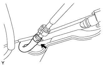
CONNECT FUEL TANK TO FILLER PIPE HOSE
Connect the fuel tank to filler pipe hose with the clamp.
Tighten the clamp bolt.
8.
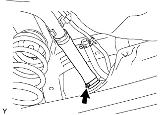
CONNECT FUEL TANK BREATHER HOSE
Connect the fuel tank breather hose with the clamp.
Tighten the clamp bolt.
9.
INSTALL FUEL TANK COVER VENT CASE SUB-ASSEMBLY
Install the fuel tank cover vent case with the bolt and clip
Torque:
5.4 N*m{
55 kgf*cm
, 48 in.*lbf
}
10.
INSTALL FRONT FLOOR HEAT INSULATOR NO. 4
Install front floor heat insulator No. 4 with the 2 nuts.
Torque:
5.4 N*m{
55 kgf*cm
, 48 in.*lbf
}
11.
INSTALL FUEL SUCTION WITH PUMP AND GAUGE TUBE ASSEMBLY
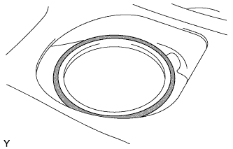
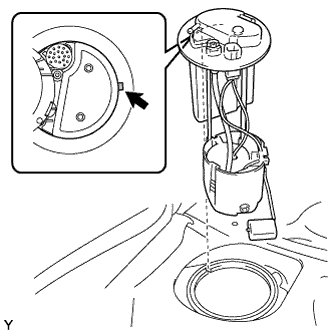
Install a new fuel suction tube gasket onto the fuel tank.
Align the protrusion of the fuel pump with the cutout of the fuel tank and install the fuel suction with pump and gauge tube assembly.
NOTICE:
The arm of the sender gauge should not be bent.
12.
INSTALL FUEL PUMP GAUGE RETAINER
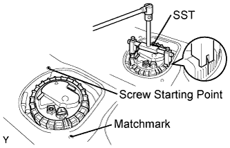
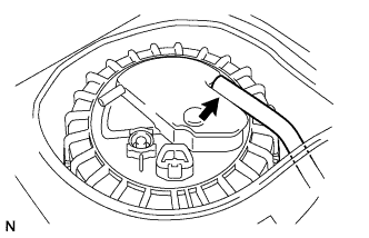
Using SST, turn the retainer 540° clockwise from the screw starting point and align the claw of the retainer with the matchmark on the fuel tank.
Replace the fuel pump gauge retainer with a new one if not installed properly.
Part No. 77144-52040
HINT:
Align the claws of the fuel pump gauge retainer and the tips of SST.
At the point where the retainer is turned 90° from the start of the thread, push the retainer in from the opposite side to the start of the thread. Check that the thread of the retainer is properly engaged with that on the fuel tank.