Remote Up / Down Function does not Operate
Circuit diagnosis · Vehicles built from Aug 2005
DESCRIPTION
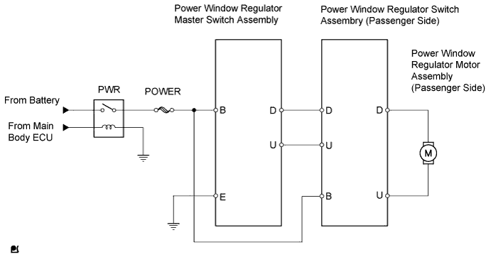
- When the engine is running or the ignition switch is on (IG), remote operation switch signals can be transmitted from the power window regulator master switch to the passenger side power window regulator switch. The passenger side power window regulator motor is driven by the passenger door power window regulator switch to which the battery voltage is supplied.
- NOTICE:
- The power window control system uses a multiplex communication system (LIN). Inspect the communication function by following HOW TO PROCEED WITH TROUBLESHOOTING. Troubleshoot the power window control system after confirming that the communication system is functioning properly.
- HINT:
- If the pulse sensor built into the power window regulator motor assembly (on the driver side) malfunctions, the power window control system enters fail-safe mode. The remote UP/DOWN and AUTO UP/DOWN functions cannot be operated during fail-safe mode. (However, the power window can be closed by holding the power window switch in the AUTO UP position and opened manually by pushing down the switch).
WIRING DIAGRAM

INSPECTION PROCEDURE
| 1. CHECK HARNESS AND CONNECTOR (POWER WINDOW MASTER SWITCH - POWER WINDOW SWITCH) |

Disconnect the G1 or F7 power window regulator master switch connector.
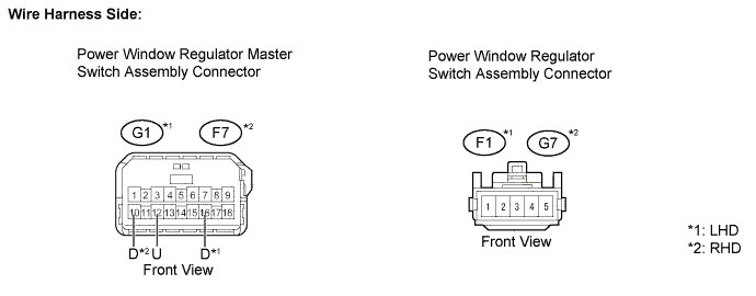
Disconnect the F1 or G7 power window regulator switch connector.
Measure the resistance of the wire harness side connectors.
- Standard resistance:
LHD Tester Connection
Specified Condition
G1-12 (U) - F1-5
Below 1 Ω
G1-16 (D) - F1-2
Below 1 Ω
G1-12 (U) or F1-5 - Body ground
10 kΩ or higher
G1-16 (D) or F1-2 - Body ground
10 kΩ or higher
RHD Tester Connection
Specified Condition
F7-12 (U) - G7-5
Below 1 Ω
F7-10 (D) - G7-2
Below 1 Ω
F7-12 (U) or G7-5 - Body ground
10 kΩ or higher
F7-10 (D) or G7-2 - Body ground
10 kΩ or higher
Reconnect the power window regulator switch connectors.
|
|
||||

| OK | ||
 |
||
| ||