REASSEMBLY
Removal / installation · Vehicles built from Jan 2006
| 1. INSTALL NO. 1 STEERING COLUMN PROTECTOR (for Manual Transaxle RHD) |

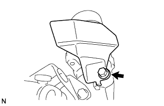  |
Install the No. 1 steering column protector with the bolt.
- Torque:
- 25 N*m{ 255 kgf*cm , 18 ft.*lbf }
| 2. INSTALL IGNITION OR STARTER SWITCH ASSEMBLY |
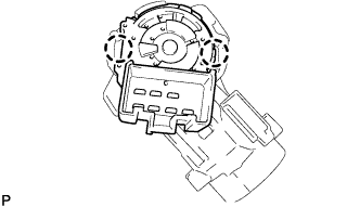 |
Engage the 2 claws to install the ignition (starter) switch assembly onto the steering column bracket assembly upper.
| 3. INSTALL KEY INTER LOCK SOLENOID |
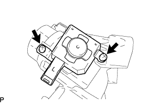 |
for Automatic Transaxle:
Install the key interlock solenoid onto the steering column bracket assembly upper with the 2 screws.
| 4. INSTALL UN-LOCK WARNING SWITCH ASSEMBLY |
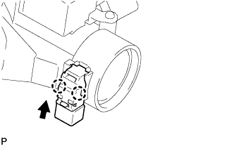 |
Engage the 2 claws to install the un-lock warning switch assembly onto the steering column bracket assembly upper.
- HINT:
- Slide the unlock warning switch assembly, in the direction shown by the arrow in the illustration, to install it.
| 5. INSTALL IGNITION SWITCH LOCK CYLINDER ASSEMBLY |
Turn the ignition switch to on (ACC).
Install the ignition switch lock cylinder assembly into the steering column bracket assembly upper.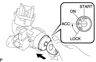
Make sure that the ignition switch lock cylinder assembly is securely fixed onto the ignition switch lock cylinder assembly.
| 6. INSPECT STEERING LOCK OPERATION |
Remove the key and check that the steering lock function is activated.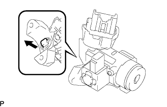
Insert the key, turn the ignition switch to on (ACC) and check that the steering lock function is inactivated.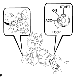
| 7. INSTALL STEERING COLUMN UPPER W/SWITCH BRACKET ASSEMBLY |
Fix the steering column assembly in a vise between aluminum plates.
- NOTICE:
- Do not overtighten the vise.
Install the steering column upper with switch bracket assembly and steering column clamp upper with 2 new steering lock set bolts, and then tighten the bolts until their heads come off.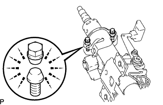
| 8. INSTALL TRANSPONDER KEY AMPLIFIER |
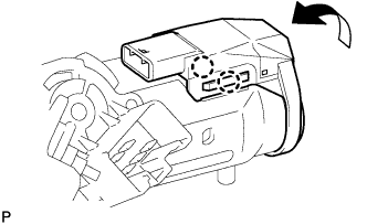 |
Engage the 2 claws and install the transponder key amplifier onto the steering column upper with the switch bracket.
| 9. INSTALL STEERING SLIDING YOKE SUB-ASSEMBLY |
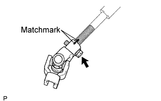
Align the matchmarks on No. 2 steering intermediate shaft assembly and steering sliding yoke and provisionally install them with the bolt.