ID Code Box Power Source Circuit
Circuit diagnosis · Vehicles built from Aug 2005
DESCRIPTION
This circuit provides power to operate the ID code box.WIRING DIAGRAM
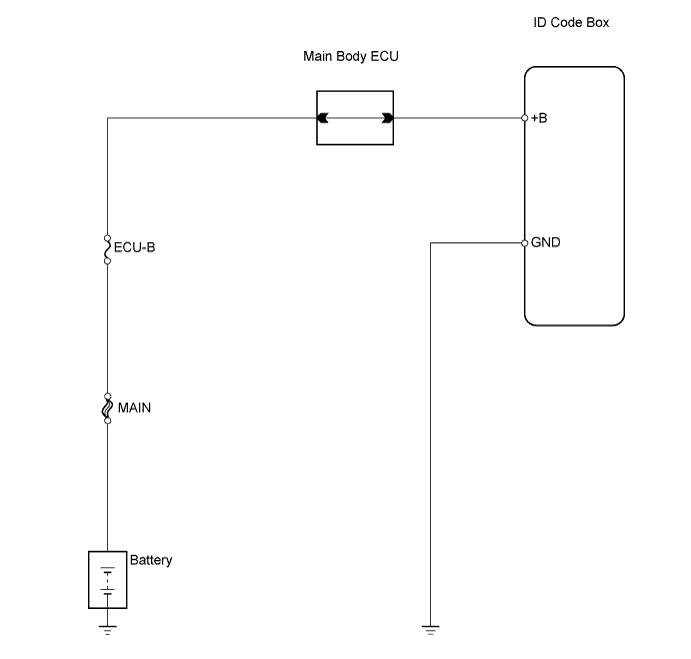

INSPECTION PROCEDURE
| 1. INSPECT FUSE (ECU-B) |

Remove the ECU-B fuse from the engine room R/B and J/B.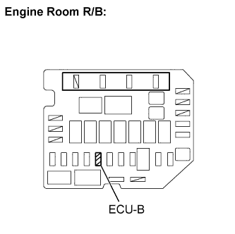
Measure the resistance.
- Standard resistance:
- Below 1 Ω
Reinstall the ECU-B fuse.
|
|
||||

| OK | |
 |
| 2. CHECK HARNESS AND CONNECTOR (ID CODE BOX - BATTERY AND BODY GROUND) |
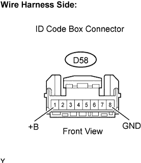 |
Disconnect the D58 ID code box connector.
Measure the resistance and voltage of the wire harness side connector.
- Standard resistance:
Tester Connection
Specified Condition
D58-8 (GND) - Body ground
Below 1 Ω
- Standard voltage:
Tester Connection
Specified Condition
D58-1 (+B) - Body ground
11 to 14 V
Reconnect the ID code box connector.
|
|
||||
| OK | ||
 |
||
| ||