Front Passenger Side Door Entry Lock and Unlock Functions do not Operate
Circuit diagnosis · Vehicles built from Aug 2005
DESCRIPTION
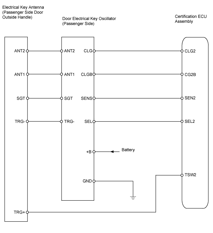
Neither the entry lock nor unlock functions operate when: 1) nothing is output from the door electrical key oscillator (passenger side), 2) the entry and start system is disabled through customization, or 3) the entire power door lock control system is malfunctioning.WIRING DIAGRAM

INSPECTION PROCEDURE
| 1. CHECK DTC OUTPUT |

Connect the intelligent tester to the DLC3.
Turn the ignition switch on (IG) and turn the tester ON.
By following the tester screen display, check whether any DTCs are output.
- OK:
- No DTC output.
|
|
||||

| OK | |
 |
| 2. CHECK MANUAL DOOR LOCK AND UNLOCK OPERATION |
Check that the manual door lock and unlock function operates normally.
- OK:
- Manual door lock and unlock function operates normally.
|
|
||||
| OK | |
|
| 3. PERFORM ACTIVE TEST BY INTELLIGENT TESTER (DOOR ELECTRICAL KEY OSCILLATOR (PASSENGER SIDE)) |
Select the Active Test, use the intelligent tester to generate a control command, and then check that the oscillator operates.
Certification ECU: Item
Test Details
Diagnostic Note
P Transmitter
Front passenger side door electrical key oscillator ON / OFF
-
- OK:
- When key is brought close to door oscillator that is OFF, indicator light on key illuminates.
|
|
||||
| NG | |
|
| 4. CHECK HARNESS AND CONNECTOR (CERTIFICATION ECU ASSEMBLY - DOOR ELECTRICAL KEY OSCILLATOR) |
Disconnect the D60 ECU connector.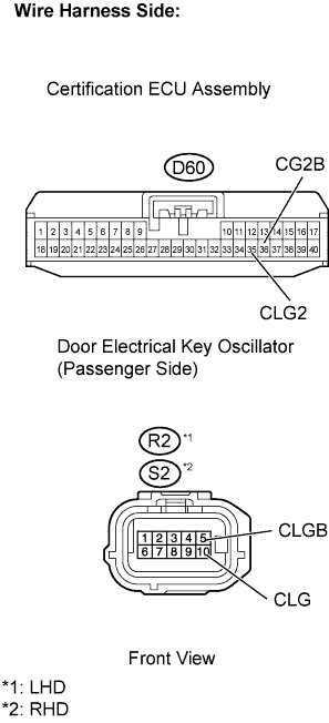
Disconnect the R2 or S2 oscillator connector.
Measure the resistance of the wire harness side connectors.
- Standard resistance:
LHD Tester Connection
Specified Condition
D60-35 (CLG2) - R2-10 (CLG)
Below 1 Ω
D60-36 (CG2B) - R2-5 (CLGB)
Below 1 Ω
RHD Tester Connection
Specified Condition
D60-35 (CLG2) - S2-10 (CLG)
Below 1 Ω
D60-36 (CG2B) - S2-5 (CLGB)
Below 1 Ω
Reconnect the ECU connector.
Reconnect the oscillator connector.
|
|
||||
| OK | |
|
| 5. CHECK HARNESS AND CONNECTOR (DOOR ELECTRICAL KEY OSCILLATOR - DOOR ELECTRICAL KEY ANTENNA) |
Disconnect the R2 or S2 oscillator connector.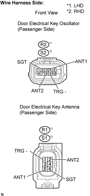
Disconnect the R1 or S1 antenna connector.
Measure the resistance of the wire harness side connectors.
- Standard resistance:
LHD Tester Connection
Specified Condition
R2-2 (SGT) - R1-6 (SGT)
Below 1 Ω
R2-3 (ANT1) - R1-5 (ANT1)
Below 1 Ω
R2-8 (ANT2) - R1-2 (ANT2)
Below 1 Ω
R2-9 (TRG-) - R1-1 (TRG-)
Below 1 Ω
RHD Tester Connection
Specified Condition
S2-2 (SGT) - S1-6 (SGT)
Below 1 Ω
S2-3 (ANT1) - S1-5 (ANT1)
Below 1 Ω
S2-8 (ANT2) - S1-2 (ANT2)
Below 1 Ω
S2-9 (TRG-) - S1-1 (TRG-)
Below 1 Ω
Reconnect the oscillator connector.
Reconnect the antenna connector.
|
|
||||
| OK | |
|
| 6. CHECK HARNESS AND CONNECTOR (+B VOLTAGE AND BODY GROUND (DOOR ELECTRICAL KEY OSCILLATOR)) |
Disconnect the R2 or S2 oscillator connector.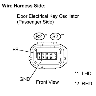
Measure the resistance of the wire harness side connector.
- Standard voltage:
LHD Tester Connection
Specified Condition
R2-1 (+B) - R2-7 (GND)
10 to 14 V
RHD Tester Connection
Specified Condition
S2-1 (+B) -S2-7 (GND)
10 to 14 V
Measure the resistance of the wire harness side connector.
- Standard resistance:
LHD Tester Connection
Specified Condition
R2-7 (GND) - body ground
10 kΩ or higher
RHD Tester Connection
Specified Condition
S2-7 (GND) - body ground
10 kΩ or higher
Reconnect the oscillator connector.
|
|
||||
| OK | |
|
| 7. CHECK HARNESS AND CONNECTOR (DOOR ELECTRICAL KEY ANTENNA - CERTIFICATION ECU ASSEMBLY) |
Disconnect the R1 or S1 antenna connector.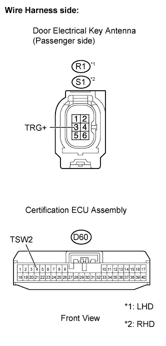
Disconnect the D60 ECU connector.
Measure the resistance of the wire harness side connectors.
- Standard resistance:
LHD Tester Connection
Specified Condition
R1-3 (TRG+) - D60-4 (TSW2)
Below 1 Ω
RHD Tester Connection
Specified Condition
S1-3 (TRG+) - D60-4 (TSW2)
Below 1 Ω
Reconnect the antenna connector.
Reconnect the ECU connector.
|
|
||||
| OK | |
|
| 8. CHECK OPERATION OF ELECTRICAL KEY ANTENNA |
After replacing the electrical key antenna (passenger side) with a normal one, check that the entry lock and unlock functions operate normally.
- OK:
- Entry lock and unlock functions operate normally.
|
|
||||
| NG | |
|
| 9. CHECK OPERATION OF DOOR ELECTRICAL KEY OSCILLATOR |
After replacing the door electrical key oscillator (passenger side) with a normal one, check that the entry lock and unlock functions operate normally.
- OK:
- Entry lock and unlock functions operate normally.
|
|
||||
| OK | ||
 |
||
| ||