Power Windows do not Operate at All
Circuit diagnosis · Vehicles built from Nov 2005
DESCRIPTION
If all of the power windows do not operate, the power window regulator master switch may have no power or may be malfunctioning.WIRING DIAGRAM
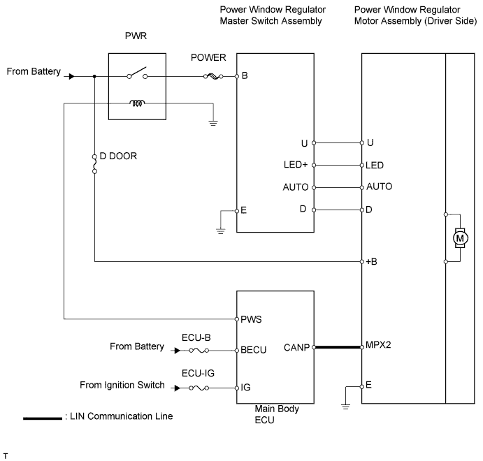

INSPECTION PROCEDURE
| 1. INSPECT FUSE (ECU-IG, ECU-B) |

Remove the ECU-B fuse from the engine room relay block.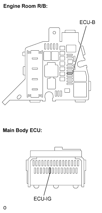
Remove the ECU-IG fuse from the main body ECU.
Measure the resistance.
- Standard resistance:
- Below 1 Ω
Reinstall the fuses.
|
|
||||

| OK | |
 |
| 2. INSPECT MAIN BODY ECU (Marking: PWR RELAY) |
Remove the POWER fuse from the main body ECU.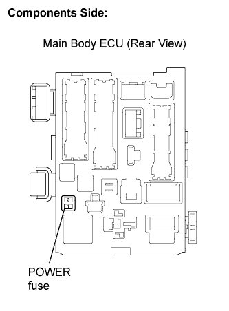
Turn the ignition switch to on (IG).
Measure the voltage between the POWER fuse terminal of the main body ECU and body ground.
- Standard resistance:
Tester Connection
Ignition Switch Conditions
Specified Condition
POWER fuse terminal (1) - Body ground
on (IG)
10 to 14 V
Reinstall the POWER fuse.
|
|
||||
| OK | |
|
| 3. CHECK WIRE HARNESS (MASTER SWITCH - BATTERY AND BODY GROUND) |
Disconnect the G1 or F7 master switch connector.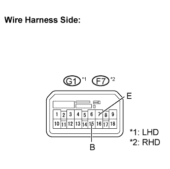
Measure the voltage of the wire harness side connector.
- Standard voltage:
LHD Tester Connection
Condition
Specified Condition
G1-15 (B) - Body ground
Ignition switch on (IG)
10 to 14 V
RHD Tester Connection
Condition
Specified Condition
F7-15 (B) - Body ground
Ignition switch on (IG)
10 to 14 V
Measure the resistance of the wire harness side connector.
- Standard resistance:
LHD Tester Connection
Specified Condition
G1-7 (E) - Body ground
Below 1 Ω
RHD Tester Connection
Specified Condition
F7-7 (E) - Body ground
Below 1 Ω
Reconnect the master switch connector.
|
|
||||
| OK | ||
 |
||
| ||