Key-off Operation Function Operates even if Operating Conditions are not Satisfied
Circuit diagnosis · Vehicles built from Nov 2005
DESCRIPTION
- When the driver door has not been opened and fully closed, each door power window regulator can control its power window operation for approximately 45 seconds after the ignition switch is turned from on (IG) to off (the key is removed), by receiving operation permission signals from the main body ECU. However, when approximately 45 seconds have elapsed or the driver door or front passenger side door is opened within approximately 45 seconds of the ignition switch being turned off (the key is removed), the power window regulator motor stops to operating.
WIRING DIAGRAM
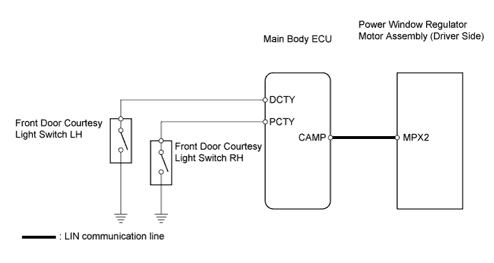

INSPECTION PROCEDURE
| 1. CHECK OPERATION FUNCTION AFTER IGNITION SWITCH IS TURNED OFF |

Check the power window operation function after the ignition switch is turned off.
Result: Status
Proceed to
When power window can still be operated even after opening driver door and passenger door within approximately 45 seconds of ignition switch being turned off
A
When power window can still be operated even after approximately 45 seconds have elapsed after ignition switch turned off
B
|
|
||||

| A | |
 |
| 2. INSPECT FRONT DOOR COURTESY SWITCH (DRIVER SIDE AND PASSENGER SIDE) |
Measure the resistance.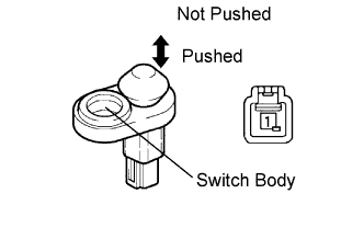
- Standard resistance:
Tester Connection
Switch Condition
Specified Condition
1 - Switch body
Pushed
10 kΩ or higher
1 - Switch body
Not Pushed
Below 1 Ω
|
|
||||
| OK | |
|
| 3. INSPECT MAIN BODY ECU |
Measure the voltage without removing the 4A main body ECU connector.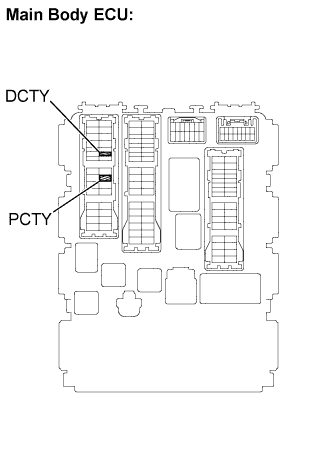
- Standard voltage:
for Driver side Main body ECU Tester Connection
Driver Door Condition
Specified Condition
4A-21 (DCTY) - Body ground
Fully closed
10 to 14V
4A-21 (DCTY) - Body ground
Open
Below 1V
for Passenger side Main body ECU Tester Connection
Driver Door Condition
Specified Condition
4A-24 (PCTY) - Body ground
Fully closed
10 to 14V
4A-14 (PCTY) - Body ground
Open
Below 1V
|
|
||||
| OK | |
|
| 4. CHECK HARNESS AND CONNECTOR (MAIN BODY ECU - POWER WINDOW REGULATOR MOTOR (DRIVER SIDE)) |
Disconnect the F8 or G8 power window motor connector.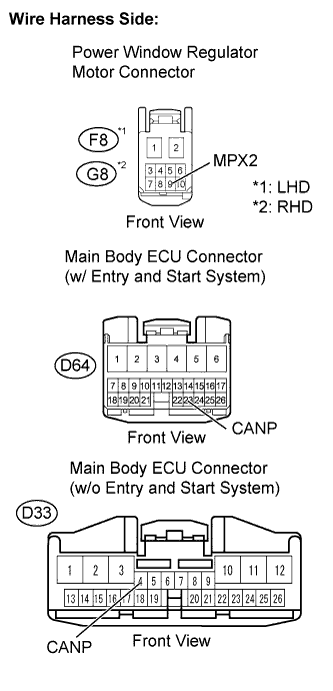
Disconnect the D64 or D33 main body ECU connector.
Measure the resistance of the wire harness side connectors.
- Standard resistance (w/ entry and start system):
LHD Tester Connection
Specified Condition
F8-9 (MPX2) - D64-23 (CANP)
Below 1 Ω
F8-9 (MPX2) or D64-23 (CANP) - Body ground
10 kΩ or higher
RHD Tester Connection
Specified Condition
G8-9 (MPX2) - D64-23 (CANP)
Below 1 Ω
G8-9 (MPX2) or D64-23 (CANP) - Body ground
10 kΩ or higher
- Standard resistance (w/o entry and start system):
LHD Tester Connection
Specified Condition
F8-9 (MPX2) - D33-4 (CANP)
Below 1 Ω
F8-9 (MPX2) or D33-4 (CANP) - Body ground
10 kΩ or higher
RHD Tester Connection
Specified Condition
G8-9 (MPX2) - D33-4 (CANP)
Below 1 Ω
G8-9 (MPX2) or D33-4 (CANP) - Body ground
10 kΩ or higher
Reconnect the power window motor connector.
Reconnect the main body ECU connector.
|
|
||||
| OK | ||
 |
||
| ||