DIAGNOSIS SYSTEM
Troubleshooting · Vehicles built from Nov 2005
| DESCRIPTION |
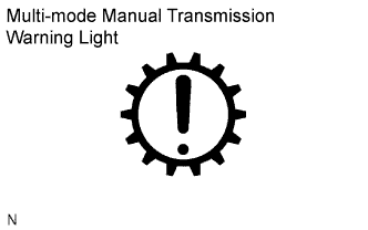  |
- The transmission control ECU has a self-diagnosis system. If the ECU, the multi-mode manual transmission system or any components fail to operate correctly, the ECU detects the malfunction, and illuminates the multi-mode manual transmission warning light on the combination meter.
The multi-mode manual transmission warning light is illuminated when the multi-mode manual transmission system malfunctions.
-
When troubleshooting Euro-OBD vehicles, the only difference from the usual troubleshooting procedure is that an OBD scan tool (complying with ISO 15765-4) or an intelligent tester is connected to the vehicle, and various data output from the vehicle ECU is read.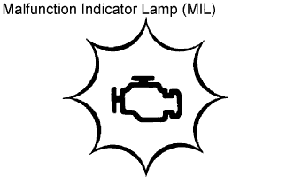
- Euro-OBD regulations require that the vehicle's on board computer illuminates the MIL (Malfunction Indicator Lamp) on the combination meter when the ECM (Engine Control Module) detects a malfunction in: 1) the emission control systems and components, or 2) the powertrain control components (which affect vehicle emissions), or 3) the ECM. Therefore, the transmission control ECU illuminates the MIL and multi-mode manual transmission warning light together if malfunctions related to these systems or components are detected.
- If the malfunction does not recur on 3 consecutive trips, the MIL goes out automatically. However, the DTCs remain recorded in the transmission control ECU memory.
-
To check DTCs, connect the OBD scan tool or intelligent tester to the DLC3 (Data Link Connector 3) on the vehicle. The OBD scan tool or intelligent tester also enables the DTCs to be erased and the freeze frame data and various forms of engine data to be checked. See the instruction manual of the OBD scan tool or intelligent tester for details.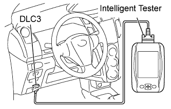
- The DTCs include ISO controlled codes and manufacturer controlled codes. ISO controlled codes must be set as prescribed by the ISO, while manufacturer controlled codes can be set by the manufacturer within prescribed limits (Click here).
| FREEZE FRAME DATA |
- Freeze frame data record the vehicle conditions (engine speed, vehicle speed, transmission gear position, shift position, etc.) when malfunctions are detected. When troubleshooting, the freeze frame data can help determine if the vehicle was moving or stationary, if the engine was warmed up or not, the transmission gear was in neutral or not, and other data, from the time the malfunction occurred.
| DLC3 (Data Link Connector 3) |
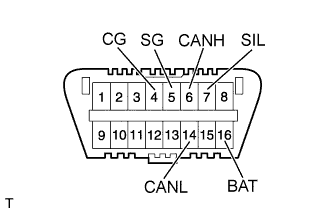 |
The ECU uses ISO 15765-4 for communication. The terminal arrangement of the DLC3 complies with ISO 15031-3 and matches the ISO 15765-4 format.
Symbol
Terminal No.
Name
Reference terminal
Result
Condition
SIL
7
Bus "+" line
5-Signal ground
Pulse generation
During transmission
CG
4
Chassis ground
Body ground
1 Ω or less
Always
SG
5
Signal ground
Body ground
1 Ω or less
Always
BAT
16
Battery positive
Body ground
9 to 14 V
Always
CANH
6
CAN "High" line
14 - CANL
54 to 69 Ω
Ignition switch off *
Battery positive
1 MΩ or higher
Ignition switch off *
4 - CG
1 kΩ or higher
Ignition switch off *
CANL
14
CAN "Low" line
Battery positive
1 MΩ or higher
Ignition switch off *
4 - CG
1 kΩ or higher
Ignition switch off *
- NOTICE:
- *: Before measuring the resistance, leave the vehicle as is for at least 1 minute and do not operate the ignition switch, any other switches or the doors.
- HINT:
- The DLC3 is the interface prepared for reading various data from the vehicle's ECU. After connecting the cable of an intelligent tester or OBD scan tool, turn the ignition switch on (IG) and turn the tester or scan tool ON.
If communication is normal: Inspect the DLC3 on the original vehicle.
If communication is impossible: The problem is probably with the tester itself. Consult the service department listed in the instruction manual.
| CHECK MULTI-MODE MANUAL TRANSMISSION WARNING LIGHT |
Turn the ignition switch on (IG).
Check that the warning light illuminates for 5 seconds. If the warning light does not illuminate, proceed to troubleshooting the multi-mode manual transmission warning light circuit (Click here).
| BATTERY VOLTAGE |
Measure the voltage of the battery.
- Standard voltage:
- 11 to 14 V
Inspect the battery, fuses, fusible links, wiring harness, connectors and ground.