INSTALLATION
Removal / installation · Vehicles built from Nov 2005
| 1. INSTALL SHIFT STROKE SENSOR |

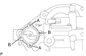  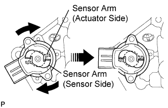 |
- NOTICE:
- Use the A holes to install the shift stroke sensor, Do not use the B holes.
Apply MP grease to a new O-ring.
Install the new O-ring onto the stroke sensor.
Set the stroke senor so that the sensor side and the actuator side sensor arms are in the positions shown in the illustration.
Turn the stroke sensor clockwise and fix it with the 2 screws.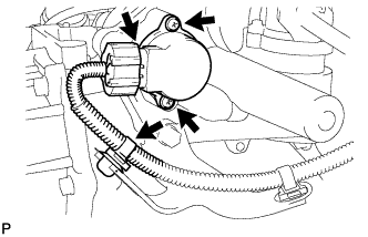
- Torque:
- 2.0 N*m{ 20 kgf*cm , 18 in.*lbf }
Connect the shift stroke sensor connector.
Connect the wire harness clamp.
| 2. INSTALL BATTERY CARRIER |
Install the battery carrier with the 5 bolts.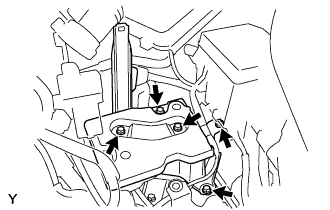
- Torque:
- 17 N*m{ 175 kgf*cm , 13 ft.*lbf }
| 3. INSTALL BATTERY TRAY |
| 4. INSTALL BATTERY |
| 5. INSTALL BATTERY HOLD DOWN CLAMP |
| 6. INSTALL AIR CLEANER ASSEMBLY |
Install the air cleaner case sub-assembly with air cleaner inlet with the 3 bolts.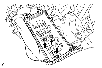
- Torque:
- 7.8 N*m{ 80 kgf*cm , 69 in.*lbf }
| 7. INSTALL NO. 1 AIR CLEANER HOSE |
Connect the No. 1 air cleaner hose with the 2 clips.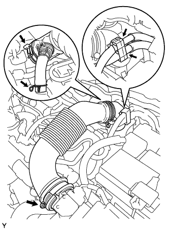
Connect the 2 fuel hoses.
Connect the No. 1 air cleaner hose with the clamp.
- Torque:
- 6.0 N*m{ 61 kgf*cm , 53 in.*lbf }
| 8. CONNECT CABLE TO NEGATIVE BATTERY TERMINAL |
- Torque:
- 5.4 N*m{ 55 kgf*cm , 48 in.*lbf }
| 9. PERFORM INITIALIZATION OF MULTI-MODE MANUAL TRANSMISSION ECU |
| 10. PERFORM LEARNING OF MULTI-MODE MANUAL TRANSMISSION SYSTEM |
| 11. PERFORM SYNCHRONIZATION POSITION CALIBRATION |