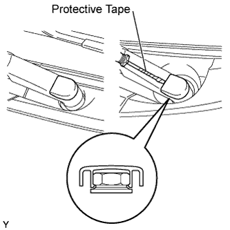
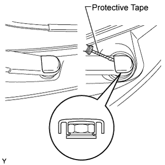
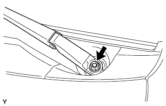
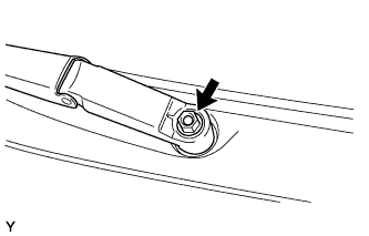
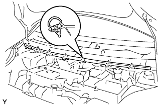
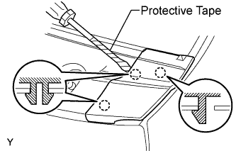
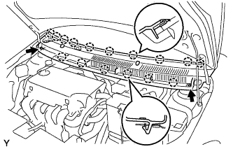
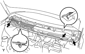
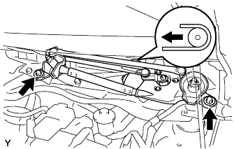
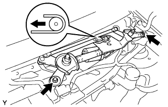
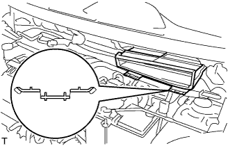
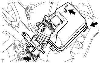
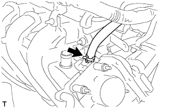
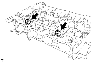
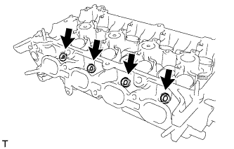
Disengage the claw and remove cowl to register duct sub-assembly No. 2.
19.
REMOVE FRONT AIR SHUTTER SEAL RH (for Sedan)
20.
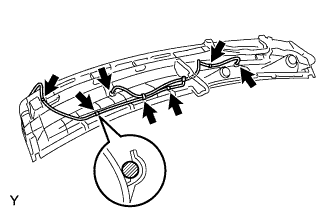
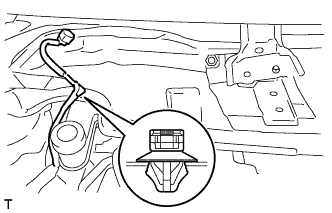
REMOVE COWL TOP PANEL OUTER (for Hatchback)
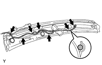
Disengage the wire harness clamp.
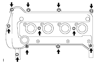
Remove the 9 bolts and remove the cowl top panel outer.
21.
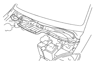
REMOVE COWL TOP PANEL OUTER (for Sedan)
22.
REMOVE BATTERY
23.
REMOVE BATTERY TRAY
24.
REMOVE FRONT WHEEL RH
25.
REMOVE ENGINE UNDER COVER RH
26.
DRAIN ENGINE OIL
27.
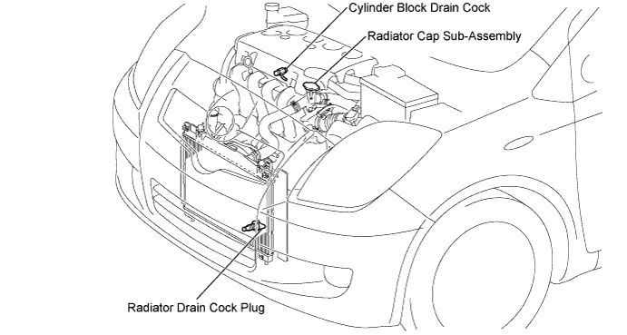
DRAIN ENGINE COOLANT
NOTICE:
To avoid the danger of being burned, do not remove the radiator cap sub-assembly while the engine and radiator assembly are still hot. Thermal expansion will cause hot engine coolant and steam to blow out from the radiator assembly.
Loosen the radiator drain cock plug.
Remove the radiator cap sub-assembly.
Loosen the cylinder block drain cock plug, then drain the coolant.
28.
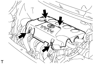
REMOVE CYLINDER HEAD COVER NO. 2
Remove the 4 nuts and cylinder head cover No. 2.
29.
REMOVE AIR CLEANER CAP SUB-ASSEMBLY WITH AIR CLEANER HOSE NO. 1
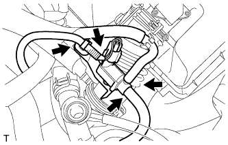
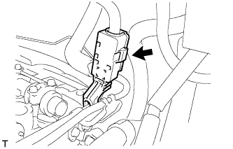
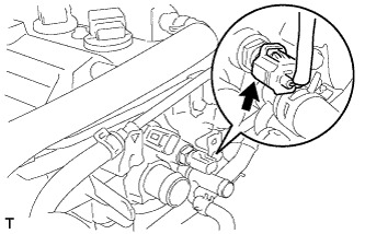
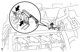
Disconnect fuel vapor feed hose No. 1 and fuel vapor feed hose No. 2 from the vacuum switching valve assembly.
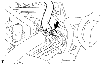
Disconnect the vacuum switching valve assembly connector and wire harness clamp.
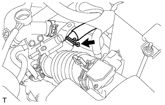
Disconnect ventilation hose No. 2.
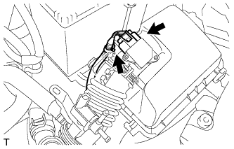
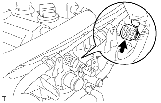
Disconnect the wire harness clamp and mass air flow meter connector.
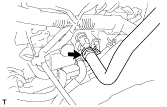
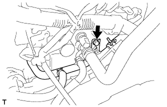
Loosen the hose clamp, unlock the air cleaner assembly clamp and remove air cleaner cap sub-assembly with air cleaner hose No. 1.
30.
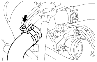
DISCONNECT RADIATOR HOSE NO. 3
Disconnect radiator hose No. 3.
31.
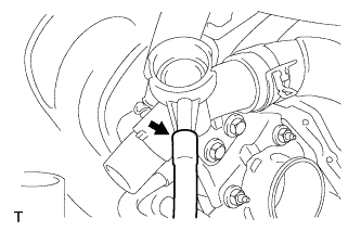
DISCONNECT RESERVE TANK HOSE
Disconnect the reserve tank hose.
32.
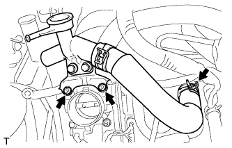
REMOVE WATER FILLER SUB-ASSEMBLY
Separate radiator hose No. 1 from the cylinder head.
Remove the 2 nuts and remove the water filler sub-assembly.
33.
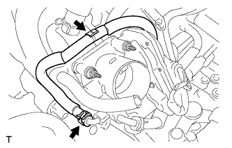
DISCONNECT WATER BY-PASS HOSE NO. 2
Disconnect water by-pass hose No. 2.
34.
DISCONNECT WATER BY-PASS HOSE
Disconnect the water by-pass hose.
35.
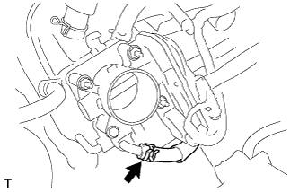
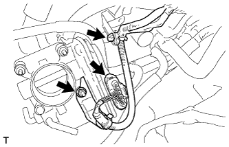
DISCONNECT THROTTLE WITH MOTOR BODY CONNECTOR
Separate the wire harness clamp.
Remove the nut and separate the throttle with motor body connector.
36.
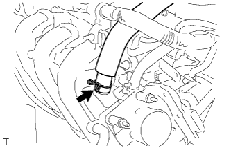
DISCONNECT VENTILATION HOSE
Disconnect the ventilation hose.
37.
DISCONNECT UNION TO CONNECTOR TUBE HOSE
Disconnect the union to connector tube hose.
38.
REMOVE OIL LEVEL GAUGE SUB-ASSEMBLY
39.
REMOVE INTAKE MANIFOLD
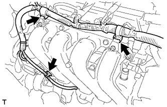
Separate the wire harness clamps shown in the illustration.
Remove the 3 bolts and 2 nuts and remove the intake manifold.
40.
REMOVE OIL LEVEL GAUGE GUIDE
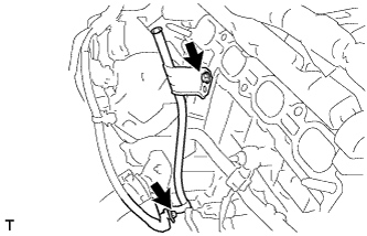
Remove the wire harness clamp and the bolt and remove the oil level gauge guide.
41.
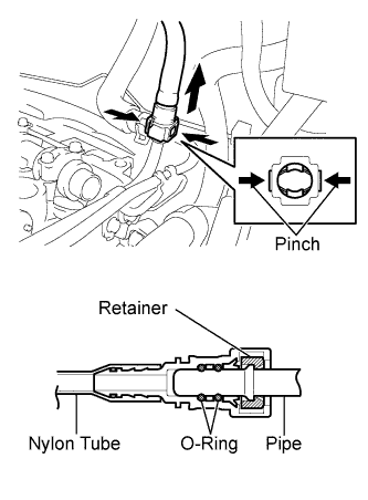
DISCONNECT FUEL TUBE SUB-ASSEMBLY
Remove the fuel pipe clamp.
Pinch the retainer of the fuel tube connector, then pull out the fuel tube connector to disconnect the fuel tube from the fuel delivery pipe sub-assembly.
NOTICE:
Remove any dirt and foreign matter from the fuel tube connector before performing this work.
Do not allow any scratches or foreign matter on the parts when disconnecting as the fuel tube connector has the O-ring that seals the pipe.
Perform this work by hand. Do not use any tools.
Do not forcibly bend, twist or turn the nylon tube.
Protect the disconnected parts by covering them with vinyl bags after disconnecting the fuel tube.
If the fuel tube connector and pipe are stuck, push and pull to release them.
42.
DISCONNECT BOOSTER VACUUM TUBE
Disconnect the booster vacuum tube.
43.
DISCONNECT CAMSHAFT POSITION SENSOR CONNECTOR
Disconnect the camshaft position sensor connector.
44.
DISCONNECT ENGINE COOLANT TEMPERATURE SENSOR CONNECTOR
Disconnect the engine coolant temperature sensor connector.
45.
DISCONNECT HEATED OXYGEN SENSOR CONNECTOR
Remove the bolts and separate the sensor bracket.
Disconnect the heated oxygen sensor connector.
46.
DISCONNECT HEATER WATER INLET HOSE A
Disconnect heater water inlet hose A.
47.
SEPARATE WATER BY-PASS PIPE NO. 1
Remove the bolt and separate water by-pass pipe No. 1.
48.
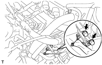
DISCONNECT WIRE HARNESS
Remove the 2 bolts and disconnect the wire harness.
49.
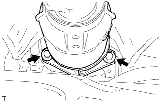
SEPARATE EXHAUST PIPE ASSEMBLY FRONT
Remove the 2 bolts and 2 compression springs and separate the exhaust pipe assembly front.
50.
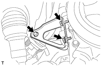
REMOVE MANIFOLD SUPPORT BRACKET
Remove the 3 bolts and remove the manifold support bracket.
51.
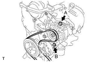
REMOVE FAN AND GENERATOR V BELT
Loosen bolts A and B.
Release the fan and generator V belt tension and remove the fan and generator V belt.
52.
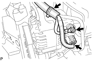
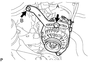
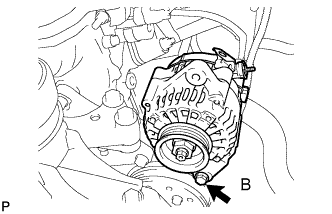
REMOVE GENERATOR ASSEMBLY
Remove the terminal cap.
Separate the connector and harness clamp.
Remove the nut and remove terminal B.
Remove fan belt adjusting slider fixing bolts A and B and remove the fan belt adjusting slider.
Remove fixing bolt B and remove the generator.
53.
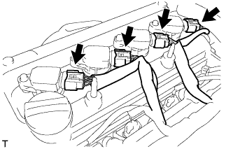
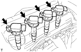
REMOVE IGNITION COIL NO. 1
Disconnect the 4 ignition coil connectors.
Remove the 4 bolts and 4 ignition coils.
54.
REMOVE VENTILATION HOSE
Disconnect the ventilation hose.
55.
REMOVE VENTILATION HOSE NO. 2
Disconnect ventilation hose No. 2.
56.
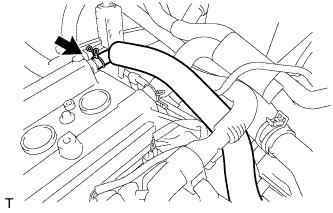
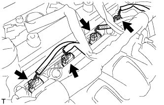
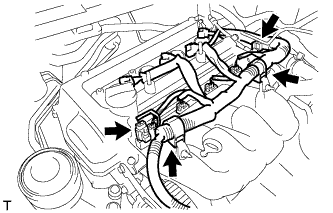
REMOVE CYLINDER HEAD COVER SUB-ASSEMBLY (for RHD)
Disconnect the fuel injector connectors.
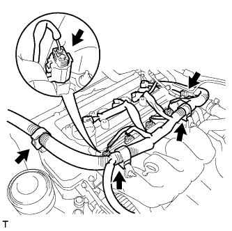
Disconnect the connector and 3 wire harness clamps shown in the illustration and disconnect the engine wire harness.
Remove the 9 bolts, 2 nuts and 2 seal washers and then remove the cylinder head cover sub-assembly.
57.
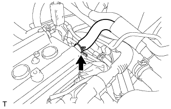
REMOVE CYLINDER HEAD COVER SUB-ASSEMBLY (for LHD)
Disconnect the fuel injector connectors.
Disconnect the connector and 3 wire harness clamps shown in the illustration and disconnect the engine wire harness.
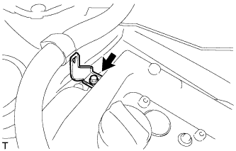
Remove the bolt and remove the wire harness bracket.
Remove the 9 bolts, 2 nuts and 2 seal washers and remove the cylinder head cover sub-assembly.
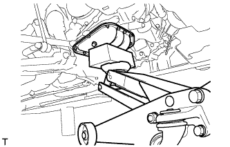
Place a wooden block on a jack underneath the engine.
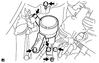
Remove the 5 bolts and nut and remove the engine mounting insulator sub-assembly RH.
59.
REMOVE CRANKSHAFT DAMPER SUB-ASSEMBLY
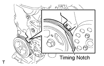
Set cylinder No. 1 to TDC/compression.
Turn the crankshaft damper sub-assembly, and align its timing notch with timing mark "0" of the oil pump.
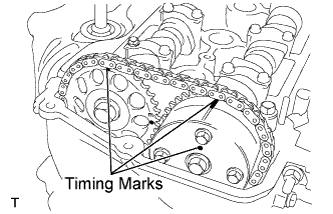
Check that the timing marks on the camshaft timing sprocket and the camshaft timing gear are all facing upward as shown in the illustration. If not, turn the crankshaft 1 complete revolution (360°) and align the marks as above.
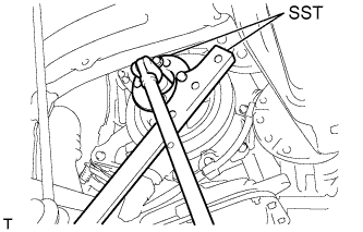
Using 2 SSTs, loosen the bolt while holding the crankshaft damper sub-assembly.
SST
09213-14010
(91651-60865)
09330-00021
NOTICE:
Check the SST installation positions when installing them, to avoid the SST fixing bolts from coming into contact with the oil pump assembly.
Remove the SSTs and the bolt.
Remove the crankshaft damper sub-assembly.
60.
REMOVE CRANKSHAFT POSITION SENSOR
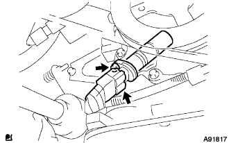
Disconnect the crankshaft position sensor connector.
Remove the bolt and remove the crankshaft position sensor.
61.
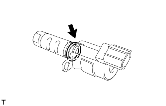
REMOVE CAMSHAFT TIMING OIL CONTROL VALVE ASSEMBLY
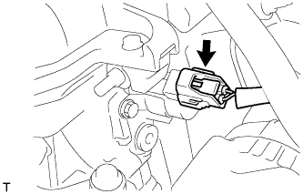
Disconnect the camshaft timing oil control valve assembly connector.
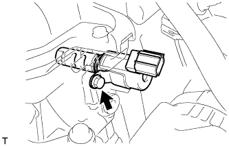
Remove the bolt and nut and remove the camshaft timing oil control valve assembly.
Remove the O-ring from the camshaft timing oil control valve assembly.
62.
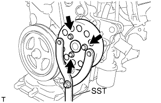
REMOVE WATER PUMP PULLEY
Using SST, hold the water pump pulley.
SST
09960-10010
(09962-01000, 09963-00700)
Remove the 3 bolts and remove the water pump pulley.
63.
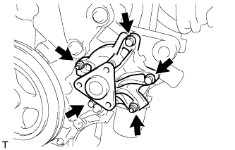
REMOVE WATER PUMP ASSEMBLY
Remove the 3 bolts and 2 nuts and remove the water pump assembly and gasket.
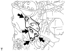
Remove the 4 bolts and remove the transverse engine engine mounting bracket.
65.
REMOVE OIL PUMP ASSEMBLY
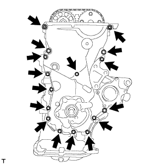
Remove the 15 bolts and the nut.
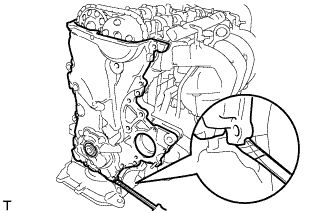
Using a screwdriver with its tip wrapped in protective tape, prize the oil pump assembly to remove it.
NOTICE:
Do not damage the contact surfaces of the oil pump assembly or oil pan sub-assembly.
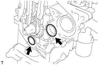
Remove the 2 O-rings from the cylinder block and oil pan sub-assembly.
66.
REMOVE OIL PUMP SEAL
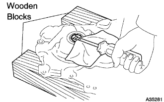
Using a screwdriver with its tip wrapped in protective tape, remove the oil pump seal.
67.
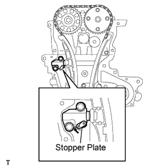
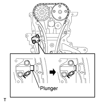
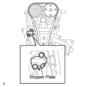
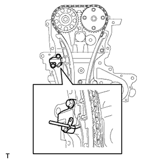
REMOVE CHAIN TENSIONER ASSEMBLY NO. 1
NOTICE:
Do not rotate the crankshaft with the chain tensioner removed.
When rotating the camshaft with the timing chain removed, rotate the crankshaft counterclockwise 40 ° from the TDC first.
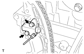
Pull up the stopper plate and hold it with its lock released.
Unlock the plunger of the tensioner and push it in to the end.
Pull down the stopper plate with the plunger pushed to the end and lock the plunger.
Insert a 3 mm (0.12 in.) diameter bar into the hole in the stopper plate and lock the plunger.
Remove the 2 bolts and remove chain tensioner assembly No. 1.
68.
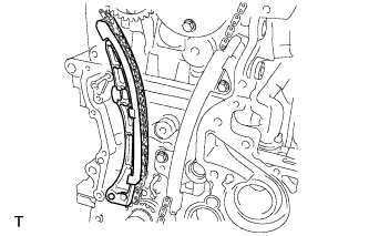
REMOVE CHAIN TENSIONER SLIPPER
Remove the chain tensioner slipper.
69.
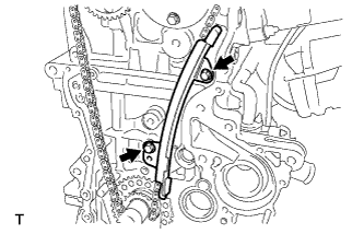
REMOVE CHAIN VIBRATION DAMPER NO. 1
Remove the 2 bolts and remove chain vibration damper No. 1.
70.
REMOVE CHAIN SUB-ASSEMBLY
71.
REMOVE CAMSHAFT
NOTICE:
When rotating the camshaft with the timing chain removed, rotate the crankshaft counterclockwise 40° from the TDC first.
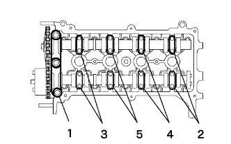
Using several steps, loosen and remove the 19 bearing cap bolts uniformly in the sequence shown in the illustration, and then remove camshaft bearing cap No. 1 and camshaft bearing cap No. 2.
NOTICE:
Loosen each bolt uniformly while keeping the camshaft level.
Remove the camshaft and camshaft No. 2.
72.
REMOVE CYLINDER HEAD SUB-ASSEMBLY
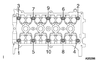
Using several steps, loosen and remove the 10 cylinder head bolts uniformly with an 8 mm bi-hexagon wrench in the sequence shown in the illustration. Remove the 10 cylinder head bolts and the plate washers.
NOTICE:
Do not drop the washers into the cylinder head.
Head warpage or cracking could result from removing the bolts in the wrong order.
73.
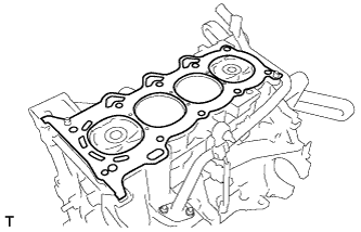
REMOVE CYLINDER HEAD GASKET
Remove the cylinder head gasket.
74.
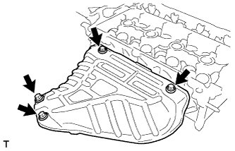
REMOVE EXHAUST MANIFOLD HEAT INSULATOR NO. 1
Remove the 4 bolts and remove exhaust manifold heat insulator No. 1.
75.
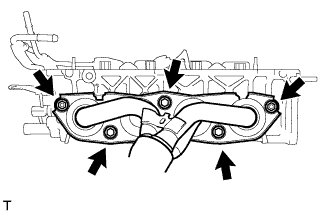
REMOVE EXHAUST MANIFOLD
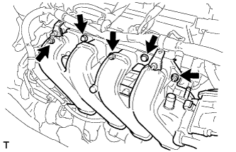
Remove the 3 bolts and 2 nuts and remove the exhaust manifold.
76.
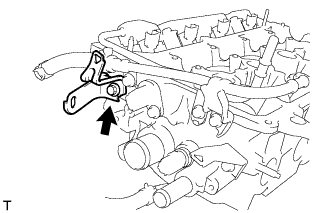
REMOVE HARNESS BRACKET
Remove the bolt and remove the harness bracket.
77.
REMOVE BOOSTER VACUUM TUBE
Remove the 2 bolts and remove the booster vacuum tube.
78.
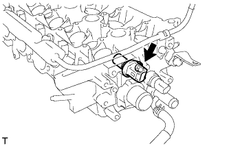
REMOVE CAMSHAFT POSITION SENSOR
Remove the bolt and remove the camshaft position sensor.
79.
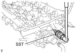
REMOVE ENGINE COOLANT TEMPERATURE SENSOR
Using SST, remove the engine coolant temperature sensor connector.
SST
09817-33190
80.
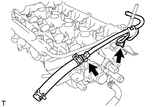
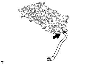
REMOVE WATER BY-PASS HOSE
Remove the water by-pass hose.
81.
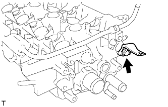
REMOVE HARNESS BRACKET
Remove the bolt and remove the harness bracket.
82.
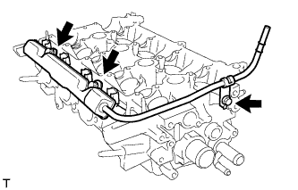
REMOVE FUEL DELIVERY PIPE SUB-ASSEMBLY
Remove the 3 bolts and remove the fuel delivery pipe sub-assembly together with the 4 fuel injectors.
NOTICE:
Do not drop the fuel injectors when removing the fuel delivery pipe sub-assembly.
83.
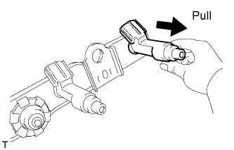
REMOVE FUEL INJECTOR ASSEMMBLY
Pull the 4 fuel injector assemblies out of the fuel delivery pipe sub-assembly.