Tachometer Malfunction
Circuit diagnosis · Vehicles built from Jan 2006
DESCRIPTION
The combination meter assembly controls the tachometer in accordance with engine speed signals from the ECM through the CAN communication system.WIRING DIAGRAM
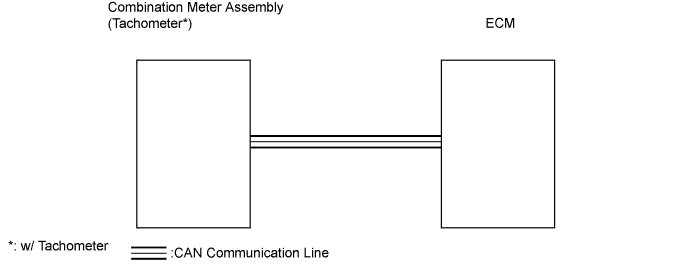

INSPECTION PROCEDURE
- HINT:
- If DTC U0100 has been stored, troubleshoot the CAN communication system first.
| 1. PERFORM ACTIVE TEST USING INTELLIGENT TESTER (TACHOMETER) |

Connect the intelligent tester to the DLC3.
Turn the ignition switch ON and turn the tester on.
Perform the Active Test according to the prompts displayed on the tester.
- Combination Meter:
Item
Test Details
Diagnostic Note
Tachometer Operation
0 rpm / 1,000 rpm / 2,000 rpm / 3,000 rpm / 4,000 rpm / 5,000 rpm / 6,000 rpm / 7,000 rpm
-
- OK:
- The engine speed displayed on the tester is approximately the same as that of the tachometer reading.
|
|
||||

| OK | |
 |
| 2. READ VALUE USING INTELLIGENT TESTER (ENGINE RPM) |
Connect the intelligent tester to the DLC3.
Turn the ignition switch ON and turn the tester on.
Read the Data List according to the prompts displayed on the tester.
- Combination Meter:
Item
Measurement Item/Range
(Display)
Normal Condition
Diagnostic Note
Engine Rpm
Engine speed / Min.: 0 rpm, Max.: 12,750 rpm
Approximately same as actual engine speed (When engine is running)
-
- OK:
- The engine speed displayed on the tester is approximately the same as the actual engine speed.
|
|
||||
| OK | ||
 |
||
| ||