INSTALLATION
Removal / installation · Vehicles built from Aug 2005
- CAUTION:
- Some of these service operations affect the SRS airbag system. Be sure to read the precautionary notices concerning the SRS airbag system before servicing (Click here).
- NOTICE:
- Always use "Torx" socket wrench E10 when installing the rear seat.
- HINT:
- The procedure described below is for the RH side. Use the same procedure for both the RH and LH sides, unless otherwise specified.
| 1. INSTALL REAR AIRBAG SENSOR |

Confirm that the ignition switch is turned to off.
Confirm that the negative battery terminal is detached.
- CAUTION:
- Confirm that the negative battery terminal is disconnected before performing the operation. Even an impact to only the airbag sensor will cause the airbag to deploy.
- Confirm that the negative battery terminal is disconnected before performing the operation. Even an impact to only the airbag sensor will cause the airbag to deploy.
Insert the hook into the body hole and install the airbag sensor with the bolt.
- Torque:
- 9.0 N*m{ 90 kgf*cm , 80 in.*lbf }
- NOTICE:
- Do not use a rear airbag sensor that has been dropped.
- Do not subject the rear airbag sensor to any impact or force.
- Do not use a rear airbag sensor that has been dropped.
Confirm that there is no looseness by shaking the rear airbag sensor.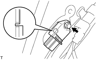

Connect the airbag connector.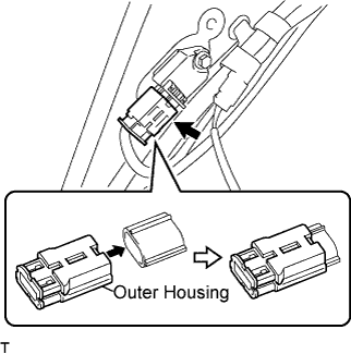
| 2. INSTALL DECK TRIM SIDE PANEL ASSEMBLY RH |
w/ Package Tray Trim: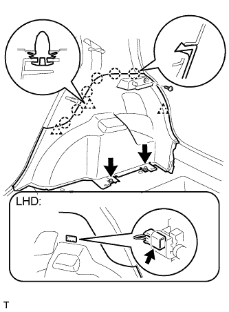
Engage the 3 clips and the 6 claws and install the deck trim side panel.
Tighten the 3 screws.
- HINT:
- When installing the deck trim side panel assembly LH onto the vehicle with the luggage compartment room light, connect the room light connector and then install the deck trim side panel assembly.
w/o Package Tray Trim: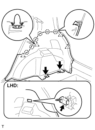
Engage the 4 clips and the 6 claws and install the deck trim side panel.
Tighten the 2 screws.
- HINT:
- When installing the deck trim side panel assembly LH onto the vehicle with the luggage compartment room light, connect the room light connector and then install the deck trim side panel assembly.
| 3. INSTALL REAR SEAT OUTER BELT ASSEMBLY RH |
Engage the clip and install the anchor plate.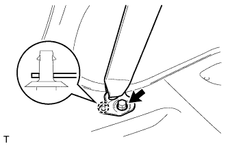
Tighten the bolt.
- Torque:
- 42 N*m{ 430 kgf*cm , 31 ft.*lbf }
Install the belt.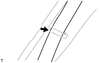
| 4. INSTALL REAR DOOR OPENING TRIM WEATHERSTRIP RH |
Install the rear door opening trim weatherstrip.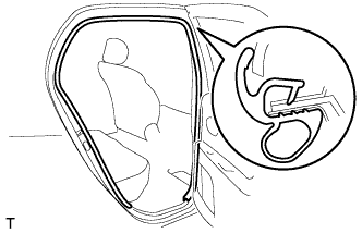
| 5. INSTALL REAR DOOR SCUFF PLATE RH |
Engage the 6 claws and install the rear door scuff plate.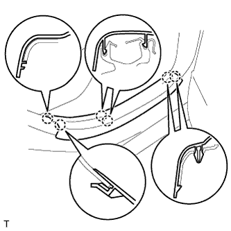
| 6. INSTALL REAR DECK TRIM COVER |
for Grand Tire: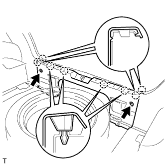
Engage the 8 claws and install the rear deck trim cover.
Install the 2 clips.
for Temper Spare Tire: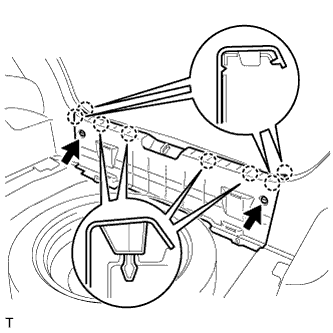
Engage the 8 claws and install the rear deck trim cover.
Install the 2 clips.
| 7. INSTALL REAR SEAT ASSEMBLY LH |
Insert the 2 location pins through the 2 body holes and install the rear seat.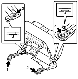
Using "Torx" socket wrench E10, install the 4 bolts in the sequence shown in the illustration.
- Torque:
- 37 N*m{ 375 kgf*cm , 27 ft.*lbf }
Install the rear seat cushion.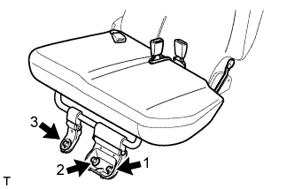
Using "Torx" socket wrench E10, install the 3 bolts in the sequence shown in the illustration.
- Torque:
- 37 N*m{ 375 kgf*cm , 27 ft.*lbf }
| 8. INSTALL REAR SEAT ASSEMBLY RH |
Insert the 2 location pins through the 2 body holes and install the rear seat.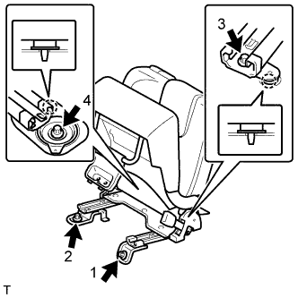
Using "Torx" socket wrench E10, install the 4 bolts in the sequence shown in the illustration.
- Torque:
- 37 N*m{ 375 kgf*cm , 27 ft.*lbf }
Install the rear seat cushion.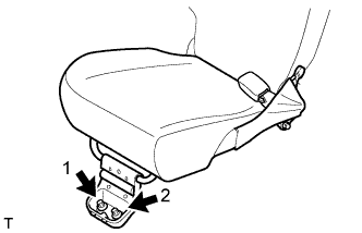
Using "Torx" socket wrench E10, install the 2 bolts in the sequence shown in the illustration.
- Torque:
- 37 N*m{ 375 kgf*cm , 27 ft.*lbf }
| 9. INSTALL NO. 2 REAR SEAT LEG COVER |
Engage the 3 claws and install the No. 2 rear seat leg cover.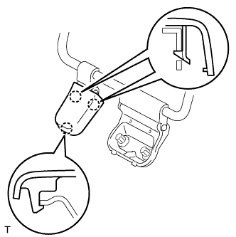
| 10. INSTALL NO. 1 REAR SEAT LEG COVER |
for RH Side:
Install the No. 1 rear seat leg cover (Click here).
for LH Side:
Install the No. 1 rear seat leg cover (Click here).
| 11. INSTALL DECK FLOOR BOX RH (w/ Deck Board) |
Set the deck floor box and lock the 2 knobs.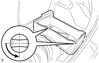
| 12. INSTALL DECK FLOOR BOX LH (w/ Deck Board) |
- HINT:
- Use the same procedure as for the RH side.
| 13. INSTALL SPARE WHEEL COVER ASSEMBLY (w/ Deck Board) |
Install the spare wheel cover.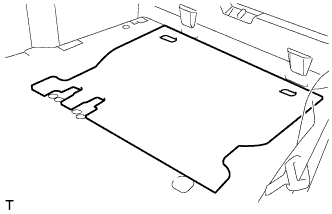
| 14. INSTALL DECK BOARD SUB-ASSEMBLY (w/ Deck Board) |
Set the deck board and lock the 2 knobs.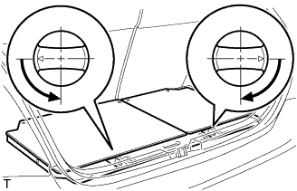
| 15. INSTALL REAR FLOOR CARPET ASSEMBLY (w/o Deck Board) |
Install the rear floor carpet.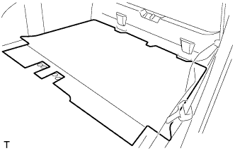
| 16. INSTALL PACKAGE TRAY TRIM PANEL ASSEMBLY (w/ Package Trim) |
Engage the 2 claws and install the package tray trim panel.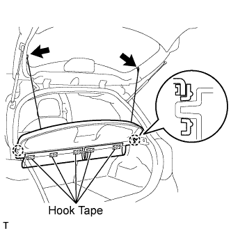
Install the 5 pieces of hook tape.
Install the 2 package tray trim suspenders.
| 17. CONNECT CABLE TO NEGATIVE BATTERY TERMINAL |
- Torque:
- 5.4 N*m{ 55 kgf*cm , 48 in.*lbf }
| 18. INSPECT SRS WARNING LIGHT |