Only Back Door LOCK / UNLOCK Functions do not Operate
Circuit diagnosis · Vehicles built from Aug 2005
DESCRIPTION
The main body ECU receives lock/unlock switch signals and activates the door lock motor accordingly.WIRING DIAGRAM
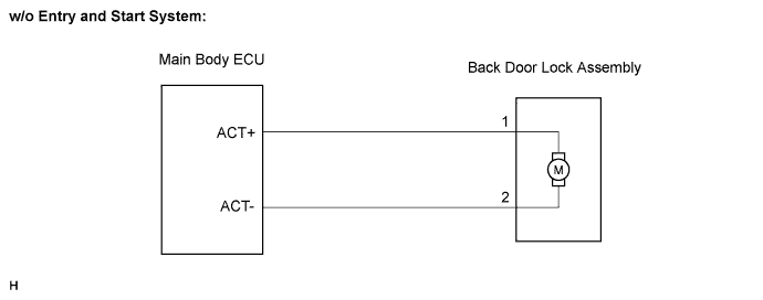

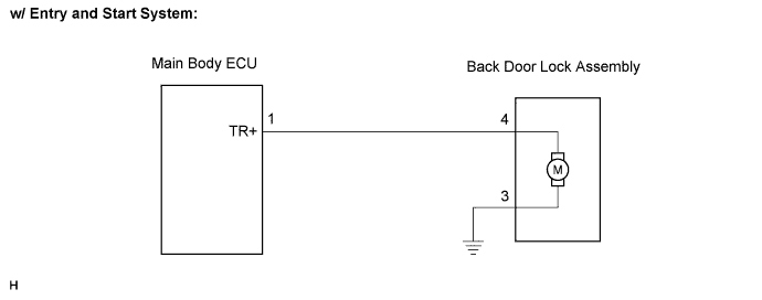
INSPECTION PROCEDURE
| 1. INSPECT BACK DOOR LOCK ASSEMBLY |

w/o Entry and start system: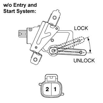
Apply the battery voltage to the door lock motor and check the operation of the door lock motor.
- OK:
Measurement Condition
Specified Condition
Battery positive (+) → Terminal 1
Battery negative (-) → Terminal 2
Lock
Battery positive (+) → Terminal 2
Battery negative (-) → Terminal 1
Unlock
w/ Entry and start system: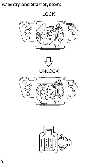
Apply the battery voltage to the door lock motor and check the operation of the door lock motor.
- OK:
Measurement Condition
Specified Condition
Battery positive (+) → Terminal 1
Battery negative (-) → Terminal 2
UNLOCK
|
|
||||

| OK | |
 |
| 2. CHECK HARNESS AND CONNECTOR (MAIN BODY ECU - BACK DOOR LOCK) |
w/o Entry and start system: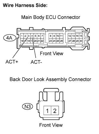
Disconnect the 4A main body ECU connector.
Disconnect the N3 door lock connector.
Measure the resistance of the wire harness side connectors.
- Standard resistance:
Tester Connection
Specified Condition
4H-3 (ACT+) - N3-1
Below 1 Ω
4H-4 (ACT-) - N3-2
Below 1 Ω
4H-3 (ACT+) or N3-1 - Body ground
10 kΩ or higher
4H-4 (ACT-) or N3-2 - Body ground
10 kΩ or higher
Reconnect the main body ECU connector.
Reconnect the door lock connector.
w/ Entry and start system: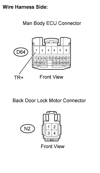
Disconnect the D64 main body ECU assembly connector.
Disconnect the N2 door lock connector.
Measure the resistance of the wire harness side connectors.
- Standard resistance:
Tester Connection
Specified Condition
D64-1 (TR+) - N2-4
Below 1 Ω
N2-3 - Body ground
Below 1 Ω
D64-1 (TR+) or N2-4 - Body ground
10 kΩor higher
Reconnect the door lock connector.
Reconnect the ECU connector.
|
|
||||
| OK | ||
 |
||
| ||