Hazard Warning Switch Circuit
Circuit diagnosis · Vehicles built from Aug 2005
DESCRIPTION
LHD models: When the hazard warning signal switch is turned on, the turn signal flasher relay in the main body ECU turns on to flash the hazard warning signal lights.RHD models: When the hazard warning signal switch is turned on, the turn signal flasher relay turns on to flash the hazard warning signal lights.
WIRING DIAGRAM
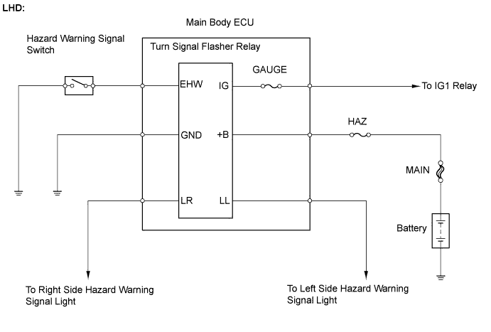

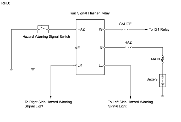
INSPECTION PROCEDURE
| 1. CHECK VEHICLE TYPE |

Check vehicle type.
- Result:
Vehicle Type
Proceed to
LHD models
A
RHD models
B
|
|
||||

| A | |
 |
| 2. INSPECT FUSE (GAUGE, HAZ) |
Remove the GAUGE fuse from the main body ECU.
Remove the HAZ fuse from the engine room relay block.
Measure the resistance.
- Standard resistance:
- Below 1 Ω
Reinstall the GAUGE and HAZ fuses.
|
|
||||

| OK | |
|
| 3. CHECK HARNESS AND CONNECTOR (FUSE - MAIN BODY ECU) |
Disconnect the 4B main body ECU connector.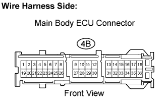
Measure the voltage.
- Standard voltage:
Tester Connection
Condition
Specified Condition
4B-32 - Body ground
Always
10 to 14 V
Reconnect the main body ECU connector.
|
|
||||
| OK | |
|
| 4. INSPECT HAZARD WARNING SIGNAL SWITCH |
Hatchback:
Remove the hazard warning signal switch.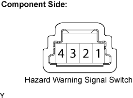
Measure the resistance.
- Standard resistance:
Tester Connection
Condition
Specified Condition
1 - 4
OFF
10 kΩ or higher
1 - 4
ON
Below 1 Ω
Reinstall the hazard warning signal switch.
Sedan:
Remove the hazard warning signal switch.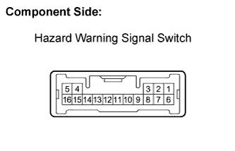
Measure the resistance.
- Standard resistance:
Tester Connection
Condition
Specified Condition
15 - 4
OFF
10 kΩ or higher
15 - 4
ON
Below 1 Ω
Reinstall the hazard warning signal switch.
|
|
||||
| OK | |
|
| 5. CHECK HARNESS AND CONNECTOR (HAZARD WARNING SIGNAL SWITCH - MAIN BODY ECU) |
Hatchback:
Disconnect the D7 hazard warning signal switch connector.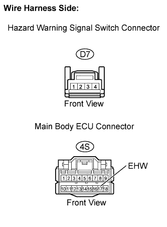
Disconnect the 4S main body ECU connector.
Measure the resistance.
- Standard resistance:
Tester Connection
Specified Condition
D7-4 - 4S-17 (EHW)
Below 1 Ω
D7-4 or 4S-17 (EHW) - Body ground
10 kΩ or higher
Reconnect the hazard warning signal switch connector.
Reconnect the main body ECU connector.
Sedan:
Disconnect the D85 hazard warning signal switch connector.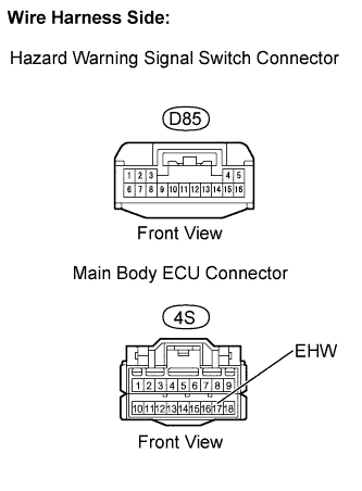
Disconnect the 4S main body ECU connector.
Measure the resistance.
- Standard resistance:
Tester Connection
Specified Condition
D85-15 - 4S-17 (EHW)
Below 1 Ω
D85-15 or 4S-17 (EHW) - Body ground
10 kΩ or higher
Reconnect the hazard warning signal switch connector.
Reconnect the main body ECU connector.
|
|
||||
| OK | |
|
| 6. CHECK HARNESS AND CONNECTOR (HAZARD WARNING SIGNAL SWITCH - BODY GROUND) |
Hatchback:
Disconnect the D7 hazard warning signal switch connector.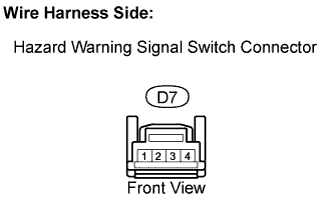
Measure the resistance.
- Standard resistance:
Tester Connection
Specified Condition
D7-1 - Body ground
Below 1 Ω
Reconnect the hazard warning signal switch connector.
Sedan:
Disconnect the D85 hazard warning signal switch connector.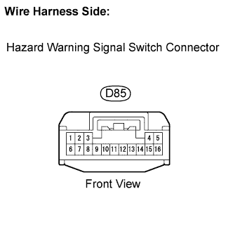
Measure the resistance.
- Standard resistance:
Tester Connection
Specified Condition
D85-4 - Body ground
Below 1 Ω
Reconnect the hazard warning signal switch connector.
|
|
||||
| OK | |
|
| 7. CHECK HARNESS AND CONNECTOR (MAIN BODY ECU - BODY GROUND) |
Disconnect the 4E main body ECU connector.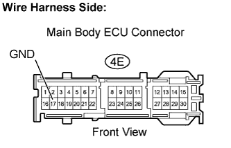
Measure the resistance.
- Standard resistance:
Tester Connection
Specified Condition
4E-17 (GND)- Body ground
Below 1 Ω
Reconnect the main body ECU connector.
|
|
||||
| OK | ||
 |
||
| ||
| 8. INSPECT FUSE (GAUGE, HAZ) |
Remove the GAUGE fuse from the main body ECU.
Remove the HAZ fuse from the engine room relay block.
Measure the resistance.
- Standard resistance:
- Below 1 Ω
Reinstall the GAUGE and HAZ fuses.
|
|
||||
| OK | |
|
| 9. INSPECT TURN SIGNAL FLASHER RELAY |
Measure the voltage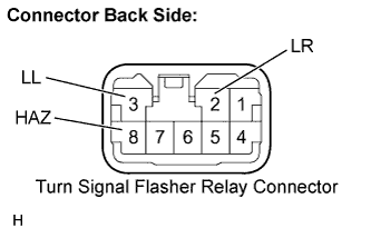
- Standard voltage:
Tester Connection
Condition
Specified Condition
D71-2 (LR) - Body ground
Hazard warning signal switch OFF → ON
0 V → 10 to 14 V (60 to 120 times per minute)
D71-3 (LL) - Body ground
Hazard warning signal switch OFF → ON
0 V → 10 to 14 V (60 to 120 times per minute)
D71-8 (HAZ) - Body ground
Hazard warning signal switch OFF → ON
10 to 14 V → 0 V
|
|
||||
| OK | |
|
| 10. INSPECT HAZARD WARNING SIGNAL SWITCH |
Hatchback:
Remove the hazard warning signal switch.
Measure the resistance.
- Standard resistance:
Tester Connection
Condition
Specified Condition
1 - 4
OFF
10 kΩ or higher
1 - 4
ON
Below 1 Ω
Reinstall the hazard warning signal switch.
Sedan:
Remove the hazard warning signal switch.
Measure the resistance.
- Standard resistance:
Tester Connection
Condition
Specified Condition
15 - 4
OFF
10 kΩ or higher
15 - 4
ON
Below 1 Ω
Reinstall the hazard warning signal switch.
|
|
||||
| OK | |
|
| 11. CHECK HARNESS AND CONNECTOR (FUSE - TURN SIGNAL FLASHER RELAY) |
Disconnect the D71 turn signal flasher connector.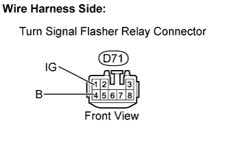
Measure the voltage.
- Standard voltage:
Tester Connection
Condition
Specified Condition
D71-1 (IG) - Body ground
Ignition switch on (IG)
10 to 14 V
D71-4 (B) - Body ground
Always
10 to 14 V
Reconnect the turn signal flasher connector.
|
|
||||
| OK | |
|
| 12. CHECK HARNESS AND CONNECTOR (TURN SIGNAL FLASHER RELAY - HAZARD WARNING SIGNAL SWITCH) |
Hatchback:
Disconnect the D7 hazard warning signal switch connector.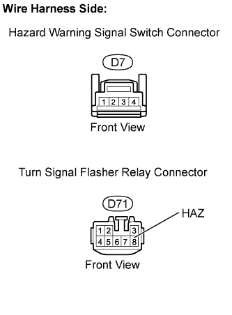
Disconnect the D71 turn signal flasher relay connector.
Measure the resistance.
- Standard resistance:
Tester Connection
Specified Condition
D7-4 - D71-8 (HAZ)
Below 1 Ω
D7-4 or D71-8 (HAZ) - Body ground
10 kΩ or higher
Reconnect the hazard warning signal switch connector.
Reconnect the turn signal flasher relay connector.
Sedan:
Disconnect the D85 hazard warning signal switch connector.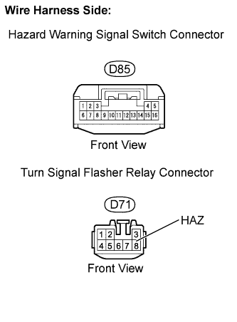
Disconnect the D71 turn signal flasher relay connector.
Measure the resistance.
- Standard resistance:
Tester Connection
Specified Condition
D85-15 - D71-8 (HAZ)
Below 1 Ω
D85-15 or D71-8 (HAZ) - Body ground
10 kΩ or higher
Reconnect the hazard warning signal switch connector.
Reconnect the turn signal flasher relay connector.
|
|
||||
| OK | |
|
| 13. CHECK HARNESS AND CONNECTOR (HAZARD WARNING SIGNAL SWITCH - BODY GROUND) |
Hatchback:
Disconnect the D7 hazard warning signal switch connector.
Measure the resistance.
- Standard resistance:
Tester Connection
Specified Condition
D7-1 - Body ground
Below 1 Ω
Reconnect the hazard warning signal switch connector.
Sedan:
Disconnect the D85 hazard warning signal switch connector.
Measure the resistance.
- Standard resistance:
Tester Connection
Specified Condition
D85-4 - Body ground
Below 1 Ω
Reconnect the hazard warning signal switch connector.
|
|
||||
| OK | ||
|
||
| ||