Back Door Entry Unlock Function does not Operate
Circuit diagnosis · Vehicles built from Aug 2005
DESCRIPTION
When the back door unlock switch is pushed, the certification ECU outputs a request signal to the outside of the vehicle through the door electrical key oscillator (back door). When the key is near the back door (within an area of approximately 1.0m (3.3ft) from the back door), it detects the request signal and responds by transmitting the ID code. The door control receiver receives the ID code and transmits it to the certification ECU. The certification ECU verifies whether the ID code is valid. When the ID code is valid, the certification ECU sends a back door open signal to the main body ECU using the multiplex communication line and stops request signal transmissions. The main body ECU then unlocks the back door.WIRING DIAGRAM
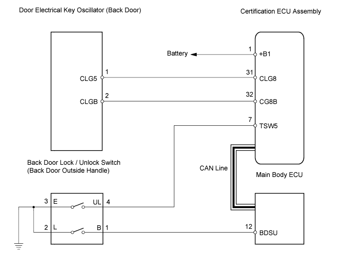

INSPECTION PROCEDURE
| 1. CHECK DTC OUTPUT |

Connect the intelligent tester to the DLC3.
Turn the ignition switch on (IG) and turn the tester ON.
By following the tester screen display, check whether any DTCs are output.
- OK:
- No DTC output.
|
|
||||

| OK | |
 |
| 2. CHECK MANUAL DOOR UNLOCK OPERATION |
Check that the manual door unlock function operates normally.
- OK:
- Manual door unlock function operates normally.
|
|
||||
| OK | |
|
| 3. CHECK WIRELESS DOOR LOCK CONTROL SYSTEM |
Check that the wireless door lock and unlock functions operates normally.
- OK:
- Wireless door lock and unlock functions operates normally.
|
|
||||
| OK | |
|
| 4. READ VALUE OF DATA LIST (BACK DOOR UNLOCK SWITCH) |
Check the Data List for proper functioning of the back door unlock switch.
- Main body ECU:
Item
Measurement Item / Range (Display)
Normal Condition
Diagnostic Note
B Dor Open SW
Back door unlock switch / ON or OFF
ON: Back door unlock switch is pushed
OFF: Back door unlock switch is not pushed
-
- OK:
- ON (back door unlock switch is pushed) appears on the screen.
|
|
||||

| OK | |
|
| 5. CHECK OPERATION OF MAIN BODY ECU |
After replacing the main body ECU with a normal one, check that the back door unlock function operates normally.
- OK:
- Back door unlock function operates normally.
|
|
||||
| OK | ||
 |
||
| ||
| 6. INSPECT BACK DOOR OUTSIDE HANDLE |
Remove the back door outside handle.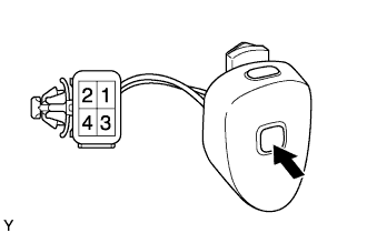
Measure the resistance.
- Standard resistance:
Tester Connection
Condition
Specified Condition
1 - 2
Switch released
10 kΩ or higher
1 - 2
Switch pressed in
Below 1 Ω
Reinstall the back door outside handle.
|
|
||||
| OK | |
|
| 7. CHECK HARNESS AND CONNECTOR (MAIN BODY ECU - BACK DOOR LOCK SWITCH) |
Disconnect the D64 main body ECU connector.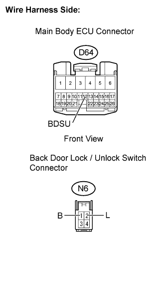
Disconnect the N6 back door lock /unlock switch connector.
Measure the resistance of the wire harness side connectors.
- Standard resistance:
Tester Connection
Specified Condition
D64-12 (BDSU) - N6-1 (B)
Below 1 Ω
N6-2 (L) - Body ground
Below 1 Ω
D64-12 (BDSU) or N6-1 (B) - Body ground
10 kΩor higher
Reconnect the switch connector.
Reconnect the ECU connector.
|
|
||||
| OK | |
|
| 8. CHECK HARNESS AND CONNECTOR (CERTIFICATION ECU ASSEMBLY - BACK DOOR LOCK SWITCH) |
Disconnect the D60 certification ECU assembly connector.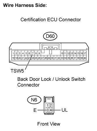
Disconnect the N6 back door lock /unlock switch connector.
Measure the resistance of the wire harness side connectors.
- Standard resistance:
Tester Connection
Specified Condition
D60-7 (TSW5) - N6-4 (UL)
Below 1 Ω
N6-3 (E) - Body ground
Below 1 Ω
D60-7 (TSW5) or N6-4 (UL) - Body ground
10 kΩor higher
Reconnect the switch connector.
Reconnect the ECU connector.
|
|
||||
| OK | |
|
| 9. CHECK OPERATION OF CERTIFICATION ECU ASSEMBLY |
After replacing the certification ECU assembly with a normal one, check that the back door unlock function operates normally.
- OK:
- Back door unlock function operates normally.
|
|
||||
| OK | ||
|
||
| ||