P0201 Injector Circuit / Open - (Cylinder 1)
Diagnostic trouble codes · Vehicles built from Nov 2005
Also covers:
- P0202 Injector Circuit / Open - (Cylinder 2)
- P0203 Injector Circuit / Open - (Cylinder 3)
- P0204 Injector Circuit / Open - (Cylinder 4)
- P2146 Fuel Injector Group "A" Supply Voltage Circuit / Open
DESCRIPTION
The injectors are installed in the cylinder head, and inject fuel into the cylinders based on the signals from the ECM.- HINT:
- Injector driver is in the ECM.
| DTC No. |
DTC Detection Conditions |
Trouble Areas |
| P0201 |
Open or short in injector circuit (cylinder No. 1) for 0.5 seconds or more (The MIL is illuminated and a DTC is immediately set when a malfunction is detected) |
|
| P0202 |
Open or short in injector circuit (cylinder No. 2) for 0.5 seconds or more (The MIL is illuminated and a DTC is immediately set when a malfunction is detected) |
|
| P0203 |
Open or short in injector circuit (cylinder No. 3) for 0.5 seconds or more (The MIL is illuminated and a DTC is immediately set when a malfunction is detected) |
|
| P0204 |
Open or short in injector circuit (cylinder No. 4) for 0.5 seconds or more (The MIL is illuminated and a DTC is immediately set when a malfunction is detected) |
|
| P2146 |
|
- HINT:
- These DTCs are set when the engine idles for approximately 15 seconds.
- If DTC P0201 is displayed, check the No. 1 injector circuit.
- If DTC P0202 is displayed, check the No. 2 injector circuit.
- If DTC P0203 is displayed, check the No. 3 injector circuit.
- If DTC P0204 is displayed, check the No. 4 injector circuit.
- These DTCs are set when the engine idles for approximately 15 seconds.
WIRING DIAGRAM
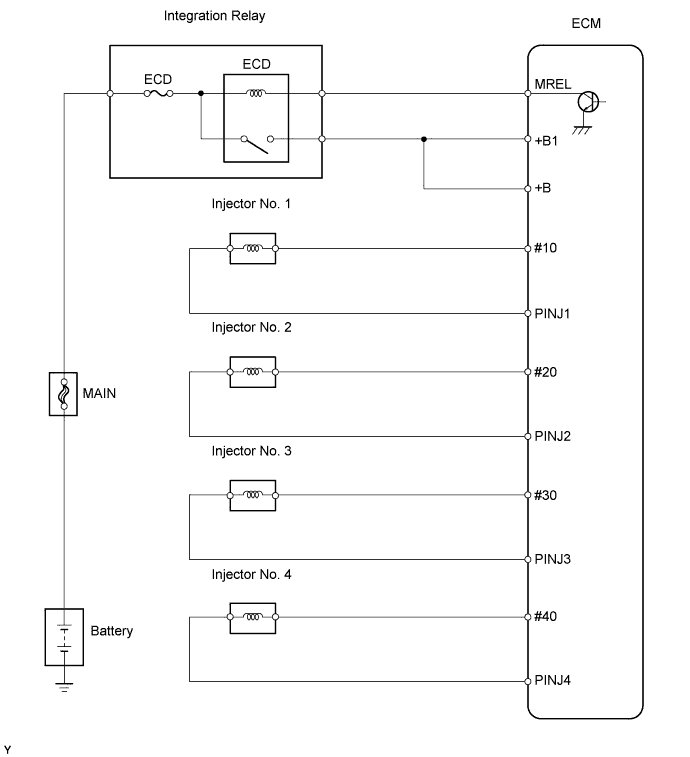

INSPECTION PROCEDURE
- HINT:
- Read freeze frame data using an intelligent tester. Freeze frame data record the engine condition when malfunctions are detected. When troubleshooting, freeze frame data can help determine if the vehicle was moving or stationary, if the engine was warmed up or not, if the air-fuel ratio was lean or rich, and other data, from the time the malfunction occurred.
| 1. READ OUTPUT DTC (DTC P0201, P0202, P0203, P0204 AND/OR P2146) |

Connect an intelligent tester to the DLC3.
Turn the ignition switch on (IG) and turn the tester on.
Select the following menu items: Powertrain / Engine and ECT / DTC.
Read DTCs.
- Result:
Display (DTC Output)
Proceed To
P0201, P0202, P0203 and/or P0204, and P2146
A
Only P2146
B
|
|
||||

| A | |
 |
| 2. INSPECT FUEL INJECTOR ASSEMBLY |
Disconnect the C45, C46, C47 and C48 injector connectors.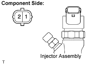
Measure the resistance between the terminals of the injector assembly.
- Standard resistance:
- 0.215 to 0.295 Ω at 20°C (68°F)
Reconnect the injector connector.
|
|
||||
| OK | |
|
| 3. CHECK HARNESS AND CONNECTOR (ECM - INJECTOR ASSEMBLY) |
Disconnect the C45, C46, C47 and C48 injector connectors.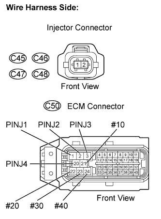
Disconnect the C50 ECM connector.
Check the resistance.
- Standard resistance (Check for open):
Tester Connections
Specified Conditions
#10 (C50-21) - (C45-2)
Below 1 Ω
#20 (C50-22) - (C46-2)
#30 (C50-23) - (C47-2)
#40 (C50-24) - (C48-2)
PINJ1 (C50-1) - (C45-1)
PINJ2 (C50-2) - (C46-1)
PINJ3 (C50-3) - (C47-1)
PINJ4 (C50-20) - (C48-1)
- Standard resistance (Check for short):
Tester Connections
Specified Conditions
#10 (C50-21) or (C45-2) - Body ground
10 kΩ or higher
#20 (C50-22) or (C46-2) - Body ground
#30 (C50-23) or (C47-2) - Body ground
#40 (C50-24) or (C48-2) - Body ground
PINJ1 (C50-1) or (C45-1) - Body ground
PINJ2 (C50-2) or (C46-1) - Body ground
PINJ3 (C50-3) or (C47-1) - Body ground
PINJ4 (C50-20) or (C48-1) - Body ground
Reconnect the injector connectors.
Reconnect the ECM connector.
|
|
||||
| OK | ||
 |
||
| ||