P0400 Exhaust Gas Recirculation Flow
Diagnostic trouble codes · Vehicles built from Nov 2005
DESCRIPTION
The EGR (Exhaust Gas Recirculation) system recirculates exhaust gases, which are controlled to the proper volume in accordance with driving conditions. The recirculated gas mingles with the intake air, therefore slowing down the engine combustion and lowering the combustion temperature. This helps reduce nitrogen oxide (NOx) emissions.In order to increase circulatory efficiency, the ECM adjusts the lift of the EGR valve and intake shutter valve (throttle valve).
| DTC No. |
DTC Detection Conditions |
Trouble Areas |
| P0400 |
Target and actual mass air flow rates differ (The MIL is illuminated and a DTC is set when the same malfunction is detected on 2 consecutive trips* *: One trip is counted when the ignition switch is turned from off to on (IG) and back to off) |
|
- HINT:
- DTC P0400 is set while the engine is running in steady condition.
- If DTC P0403 has already been set, P0400 is not set.
- DTC P0400 is set while the engine is running in steady condition.
WIRING DIAGRAM
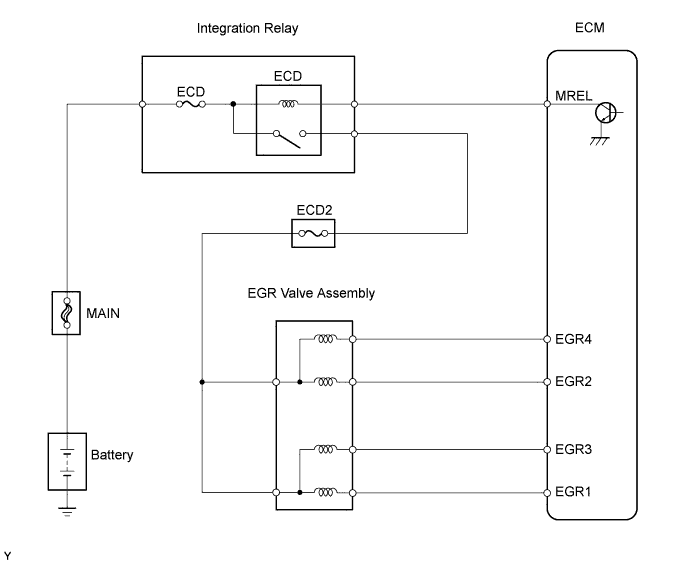

INSPECTION PROCEDURE
- HINT:
- Read freeze frame data using an intelligent tester. Freeze frame data record the engine condition when malfunctions are detected. When troubleshooting, freeze frame data can help determine if the vehicle was moving or stationary, if the engine was warmed up or not, if the air-fuel ratio was lean or rich, and other data, from the time the malfunction occurred.
| 1. CHECK ANY OTHER DTCS OUTPUT (IN ADDITION TO DTC P0400) |

Connect an intelligent tester to the DLC3.
Turn the ignition switch on (IG) and turn the tester on.
Select the following menu items: Powertrain / Engine and ECT / DTC.
Read DTCs.
- Result:
Display (DTC Output)
Proceed To
P0400
A
P0400 and other DTCs
B
- HINT:
- If any DTCs other than P0400 are output, troubleshoot those DTCs first.
|
|
||||

| A | |
 |
| 2. INSPECT EGR VALVE ASSEMBLY |
Disconnect C52 EGR valve connector.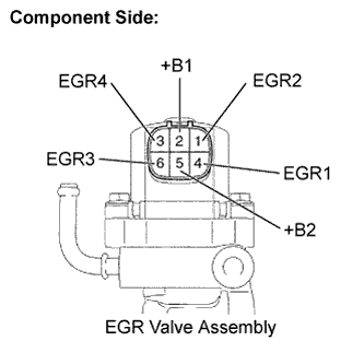
Measure the resistance between the terminals of the EGR valve connector.
- Standard resistance:
Tester Connections
Specified Conditions
+B2 (5) - EGR1 (4)
18.2 to 21.0 Ω at 20°C (68°F)
+B2 (5) - EGR3 (6)
+B1 (2) - EGR2 (1)
+B1 (2) - EGR4 (3)
|
|
||||
| OK | |
|
| 3. CHECK HARNESS AND CONNECTOR (EGR VALVE ASSEMBLY - ECM) |
Disconnect the C52 EGR valve connector.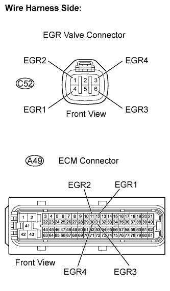
Disconnect the A49 EGR valve connector.
Check the resistance.
- Standard resistance (Check for open):
Tester Connections
Specified Conditions
EGR1 (A49-12) - EGR1 (C52-4)
Below 1 Ω
EGR2 (A49-11) - EGR2 (C52-1)
EGR3 (A49-31) - EGR3 (C52-6)
EGR4 (A49-30) - EGR4 (C52-3)
- Standard resistance (Check for short):
Tester Connections
Specified Conditions
EGR1 (A49-12) or EGR1 (C52-4) - Body ground
10 kΩ higher
EGR2 (A49-11) or EGR2 (C52-1) - Body ground
EGR3 (A49-31) or EGR3 (C52-6) - Body ground
EGR4 (A49-30) or EGR4 (C52-3) - Body ground
Reconnect the EGR valve connector.
Reconnect the ECM connector.
|
|
||||
| OK | |
|
| 4. INSPECT ECM (EGR VOLTAGE) |
Disconnect the C52 EGR valve connector.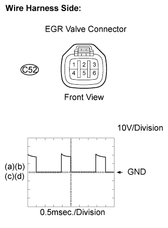
Inspect the ECM using an oscilloscope.
While repeating quick engine RPM accelerations, check the waveform between the terminals of the C52 EGR valve connector.
- Standard:
Tester Connections
Specified Conditions
EGR1 (C52-4) - Body ground
Correct waveform shown
EGR2 (C52-1) - Body ground
EGR3 (C52-6) - Body ground
EGR4 (C52-3) - Body ground
Reconnect the EGR valve connector.
|
|
||||
| OK | |
|
| 5. CHECK FOR DEPOSIT (EGR VALVE ASSEMBLY) |
- OK:
- No deposit
|
|
||||
| OK | |
|
| 6. CHECK FOR DEPOSIT (EGR PASSAGE) |
- OK:
- No deposit
|
|
||||
| OK | |
|
| 7. CHECK FOR EXHAUST GAS LEAKS |
- OK:
- No leakage
|
|
||||
| OK | |
|
| 8. INSPECT DIESEL THROTTLE BODY ASSEMBLY |
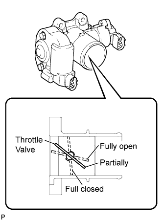 |
- NOTICE:
- Perform this inspection with the engine off.
Turn the ignition switch off.
Remove the air cleaner hose.
Visually confirm the position of the throttle valve in the diesel throttle body assembly.
- OK:
- Partially open
Turn the ignition switch on.
Visually confirm the position of the throttle valve in the diesel throttle body assembly.
- OK:
- Fully open
Visually confirm the motion of the throttle valve in the diesel throttle body assembly when the ignition switch is turned from ON to OFF.
- OK:
- Throttle valve should move from fully open to fully closed and then to partially open.
|
|
||||
| OK | |
|
| 9. READ VALUE USING INTELLIGENT TESTER (MAF) |
- NOTICE:
- Perform the inspection with the vehicle indoors and on a level surface.
- Perform the inspection of the MAF meter while it is installed to the air cleaner case (installed to the vehicle).
- During the test, do not use the exhaust air duct to perform suction on the exhaust pipe.
- Perform the inspection with the vehicle indoors and on a level surface.
Turn the ignition switch on (IG).
- NOTICE:
- Do not run the engine.
Turn the tester on.
Select the following menu items: Powertrain / Engine and ECT / Data List / Primary / MAF.
Wait 30 seconds, and read the values on the tester.
- Standard:
- Less than 0.23 g/sec.
|
|
||||
| OK | ||
 |
||
| ||