P0685 ECM / PCM Power Relay Control Circuit / Open
Diagnostic trouble codes · Vehicles built from Nov 2005
DESCRIPTION
The battery supplies power to terminal +B and/or +B1 of the ECM even when the ignition switch is turned to off (up to 15 seconds).| DTC No. |
DTC Detection Conditions |
Trouble Areas |
| P0685 |
|
|
- HINT:
- DTC P0685 is set when the ignition switch is turned to off.
- If DTC P0685 is set, the ECM does not store other DTCs.
- DTC P0685 is set when the ignition switch is turned to off.
WIRING DIAGRAM
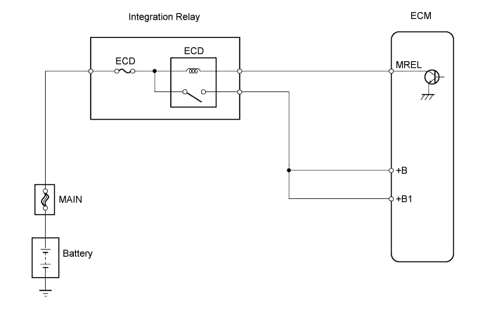

INSPECTION PROCEDURE
| 1. INSPECT INTEGRATION RELAY (ECD FUSE AND ECD RELAY) |

Remove the integration relay from the engine room relay block.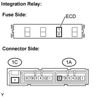
Inspect the ECD fuse.
Remove the ECD fuse from the integration relay.
Check the ECD fuse resistance.
- Standard resistance:
- Below 1 Ω
Reinstall the ECD fuse.
Inspect the ECD relay.
Check the ECD relay resistance.
- Standard resistance:
Tester Connections
Specified Conditions
1C-1 - 1A-8
10 kΩ or higher
Below 1 Ω
(Apply battery voltage between terminals 1C-1 and 1A-7)
Reinstall the integration relay.
|
|
||||

| OK | |
 |
| 2. CHECK HARNESS AND CONNECTOR (ECD RELAY - ECM, ECD FUSE - BATTERY) |
Check the harness connectors between the ECD relay and ECM.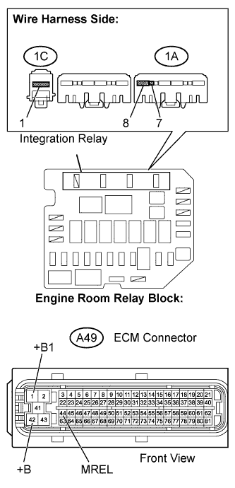
Remove the integration relay from the engine room relay block.
Disconnect the A49 ECM connector.
Check the resistance.
- Standard resistance (Check for open):
Tester Connections
Specified Conditions
Integration relay (1A-7) - MREL (A49-44)
Below 1 Ω
Integration relay (1A-8) - +B (A49-42)
Integration relay (1A-8) - +B1 (A49-1)
- Standard resistance (Check for short):
Tester Connections
Specified Conditions
Integration relay (1A-7) or MREL (A49-44) - Body ground
10 kΩ or higher
Integration relay (1A-8) or +B (A49-42) - Body ground
Integration relay (1A-8) or +B1 (A49-1) - Body ground
Reinstall the integration relay.
Reconnect the ECM connector.
Check the harness and connector between the ECD fuse and battery.
Remove the integration relay from the engine room relay block.
Disconnect the positive battery cable.
Check the resistance.
- Standard resistance (Check for open):
Tester Connections
Specified Conditions
Positive battery cable terminal - Integration relay (1C-1)
Below 1 Ω
- Standard resistance (Check for short):
Tester Connections
Specified Conditions
Positive battery cable terminal or Integration relay (1C-1) - Body ground
10 kΩ or higher
Reinstall the integration relay.
Reconnect the battery cable.
|
|
||||
| OK | ||
 |
||
| ||