INSPECTION
Inspection · Vehicles built from Nov 2005
| INSPECT CYLINDER HEAD FOR WARPAGE |

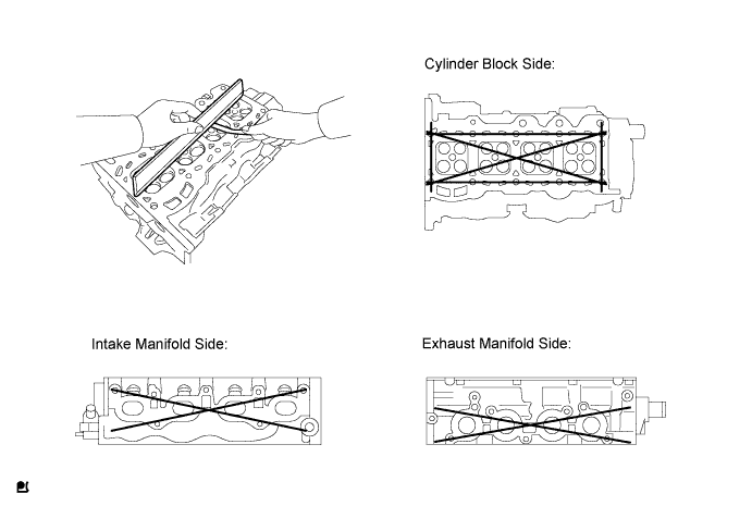
Using a precision straight edge and feeler gauge, measure the warpage of the surface that is in contact with the cylinder block and the manifolds.
- Maximum warpage:
- 0.05 mm (0.0020 in.)

| INSPECT CYLINDER HEAD FOR CRACKS |
Using a dye penetrant, check the combustion chamber, intake ports, exhaust ports and cylinder block surface for cracks.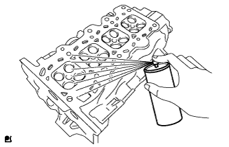
If cracked, replace the cylinder head.
| INSPECT INTAKE VALVE SEAT |
Apply a light coat of prussian blue to the valve face.
Lightly press the valve against the seat.
- NOTICE:
- Do not rotate the valve.
Remove the valve and check the valve seat contact area and width.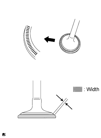
- Contact area:
- At the middle, all around the valve.
- Contact width:
- 1.0 to 1.4 mm (0.039 to 0.055 in.)
- If blue appears 360 ° around the face, the valve is concentric. If not, replace the valve.
- If blue appears 360 ° around the valve seat, the guide and face are concentric. If not, resurface the seat.
| INSPECT EXHAUST VALVE SEAT |
Apply a light coat of prussian blue to the valve face.
Lightly press the valve against the seat.
- NOTICE:
- Do not rotate the valve.
Remove the valve and check the valve seat contact area and width.
- Contact area:
- At the middle, all around the valve.
- Contact width:
- 1.0 to 1.4 mm (0.039 to 0.055 in.)
- If blue appears 360 ° around the face, the valve is concentric. If not, replace the valve.
- If blue appears 360° around the valve seat, the guide and face are concentric. If not, resurface the seat.
| INSPECT CYLINDER HEAD SET BOLT |
Using vernier calipers, measure the minimum diameter of the elongated thread at measuring point A.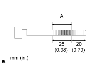
- Minimum outside diameter:
- 8.75 mm (0.3445 in.)
- HINT:
- If the outside diameter is less than the minimum, replace the cylinder head set bolt.
| INSPECT VALVE LIFTER |
Using a micrometer, measure the valve lifter diameter.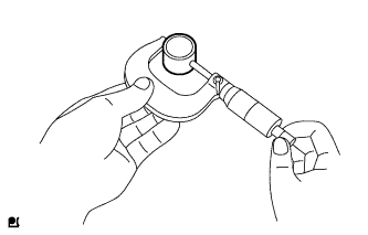
- Standard valve lifter diameter:
- 27.965 to 27.975 mm (1.1010 to 1.1014 in.)
| INSPECT VALVE LIFTER OIL CLEARANCE |
Using a caliper gauge, measure the valve lifter bore diameter of the cylinder head.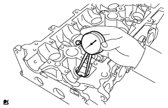
- Standard valve lifter bore diameter:
- 28.000 to 28.021 mm (1.10236 to 1.10319 in.)
Subtract the lifter diameter measurement from the lifter bore diameter measurement.
- Standard oil clearance:
- 0.015 to 0.046 mm (0.00059 to 0.00181 in.)
- Maximum oil clearance:
- 0.10mm (0.0039 in.)
| INSPECT INNER COMPRESSION SPRING |
Using vernier calipers, measure the free length of the inner compression spring.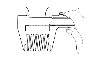
- Standard free length:
- 44.11 mm (1.7366 in.)
Using a steel square, measure the deviation of the inner compression spring.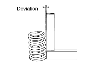
- Maximum deviation:
- 1.6 mm (0.063 in.)
- Maximum angle (reference):
- 2°
Using a spring tester, measure the tension of the inner compression spring at the specified installed length.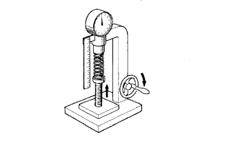
- Standard installation tension:
- 139.0 to 155.0 N (14.2 to 15.8 kgf, 31.2 to 34.8 lbf) at 37.7 mm (1.484 in.)
- Maximum working tension:
- 354 to 392 N (36.1 to 40.0 kgf, 79.6 to 88.1 lbf) at 30.5 mm (1.201 in.)
| INSPECT INTAKE VALVE |
Check the overall length.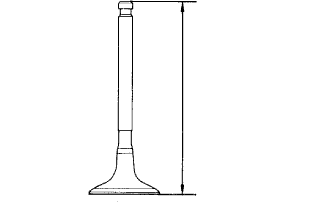
Check the overall valve length.
- Standard overall length:
- 88.15 mm (3.4705 in.)
- Minimum overall length:
- 87.85 mm (3.4587 in.)
Check the outer diameter.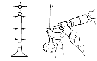
Using a micrometer, measure the diameter of the valve stem.
- Standard valve stem diameter:
- 4.975 to 4.990 mm (0.19587 to 0.19646 in.)
Check the thickness.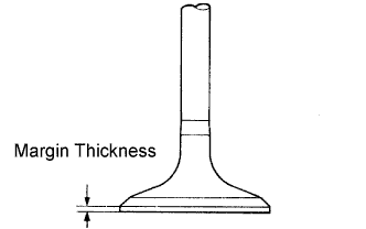
Check the valve head margin thickness.
- Standard margin thickness:
- 0.6 to 1.0 mm (0.024 to 0.039 in.)
- Minimum margin thickness:
- 0.5 mm (0.020 in.)
| INSPECT EXHAUST VALVE |
Check the overall length.
Check the overall valve length.
- Standard overall length:
- 89.10 mm (3.5079 in.)
- Minimum overall length:
- 88.80 mm (3.4961 in.)
Check the outer diameter.
Using a micrometer, measure the diameter of the valve stem.
- Standard valve stem diameter:
- 4.965 to 4.980 mm (0.19547 to 0.19606 in.)
Check the thickness.
Check the valve head margin thickness.
- Standard margin thickness:
- 0.8 to 1.2 mm (0.024 to 0.039 in.)
- Minimum margin thickness:
- 0.7 mm (0.028 in.)
| INSPECT VALVE GUIDE BUSH OIL CLEARANCE |
Using a caliper gauge, measure the inside diameter of the valve guide bush.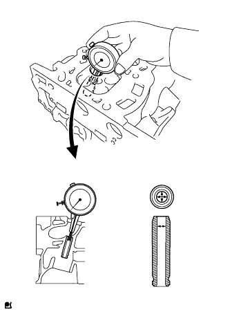
- Bush inside diameter:
- 5.010 to 5.022 mm (0.19724 to 0.19772 in.)
Subtract the valve stem diameter measurement from the guide bush inside diameter measurement.
- Standard oil clearance:
Guide Bush
Specified Condition
Intake
0.020 to 0.047 mm
(0.00079 to 0.00185 in.)
Exhaust
0.030 to 0.057 mm
(0.00118 to 0.00224 in.)
- Maximum oil clearance:
Guide Bush
Specified Condition
Intake
0.06 mm (0.0024 in.)
Exhaust
0.08 mm (0.0032 in.)
| INSPECT CAMSHAFT |
Inspect the camshaft for runout.
Place the camshaft on V-blocks.
Using a dial indicator, measure the circle runout at the center journal.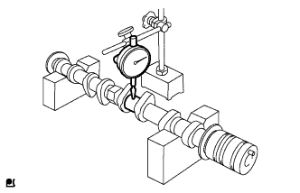
- Maximum circle runout:
- 0.03 mm (0.0012 in.)
Inspect the cam lobes.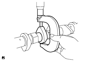
Using a micrometer, measure the cam lobe height.
- Standard cam lobe height:
- 23.83 to 23.93 mm (0.9382 to 0.9421 in.)
- Minimum cam lobe height:
- 23.73 mm (0.9343 in.)
Inspect the camshaft journals.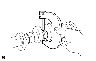
Using a micrometer, measure the journal diameter.
- Standard journal diameter:
Journal
Specified Condition
No. 1 journal
33.984 to 34.000 mm
(1.33795 to 1.33858 in.)
Other journals
22.979 to 22.995 mm
(0.90469 to 0.90531 in.)
| INSPECT NO.2 CAMSHAFT |
Inspect the No. 2 camshaft for runout.
Place the camshaft on V-blocks.
Using a dial indicator, measure the circle runout at the center journal.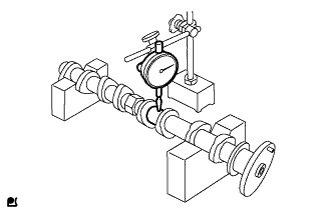
- Maximum circle runout:
- 0.03 mm (0.0012 in.)
Inspect the cam lobes.
Using a micrometer, measure the cam lobe height.
- Standard cam lobe height:
- 23.40 to 23.50 mm (0.9213 to 0.9252 in.)
- Minimum cam lobe height:
- 23.30 mm (0.9173 in.)
Inspect the No. 2 camshaft journals.
Using a micrometer, measure the journal diameter.
- Standard journal diameter:
Journal
Specified Condition
No. 1 journal
25.979 to 25.995 mm
(1.02280 to 1.02343 in.)
Other journals
22.979 to 22.995 mm
(0.90469 to 0.90531 in.)
| INSPECT CAMSHAFT THRUST CLEARANCE |
Examine the front marks and numbers and check that the sequence is as shown in the illustration. Then provisionally tighten the bolts.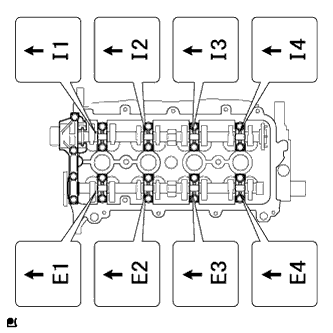
Uniformly tighten the bolts in several steps in the sequence shown in the illustration.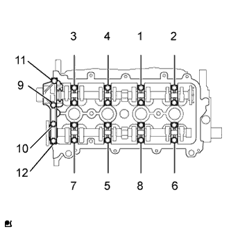
- Torque:
- 13 N*m{ 127 kgf*cm , 9 ft.*lbf }
- NOTICE:
- Tighten each bolt uniformly while keeping the camshaft level.
Using a dial indicator, measure the thrust clearance while moving the camshaft back and forth.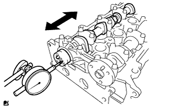
- Standard thrust clearance:
- 0.10 to 0.24 mm (0.0039 to 0.0095 in.)
- Maximum thrust clearance:
- 0.26 mm (0.0102 in.)
| INSPECT CAMSHAFT OIL CLEARANCE |
- NOTICE:
- Do not turn the camshaft.
Install the camshafts.
Lay a strip of Plastigage across each camshaft journal.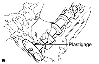
Examine the front marks and numbers and check that the sequence is as shown in the illustration. Then provisionally tighten the bolts.
Uniformly tighten the bolts in several steps in the sequence shown in the illustration.
- Torque:
- 13 N*m{ 127 kgf*cm , 9 ft.*lbf }
- NOTICE:
- Tighten the bolts uniformly while keeping the camshaft level.
Using several steps, loosen and remove the 20 bearing cap bolts uniformly in the sequence shown in the illustration.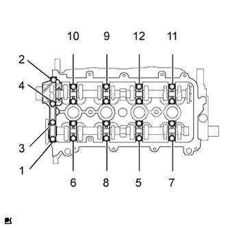
- NOTICE:
- Loosen the bolts uniformly while keeping the camshaft level.
Measure the Plastigage at its widest point.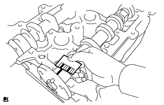
- Standard oil clearance:
Journal
Specified Condition
Intake No. 1 journal
0.025 to 0.061 mm
(0.00098 to 0.00240 in.)
Other journals
0.037 to 0.073 mm
(0.00146 to 0.00287 in.)
- Maximum oil clearance:
Journal
Specified Condition
Intake No. 1 journal
0.09 mm (0.0035 in.)
Other journals
0.10 mm (0.0039 in.)
- NOTICE:
- Completely remove the Plastigage.