Removal / installation · Vehicles built from Nov 2005
1.
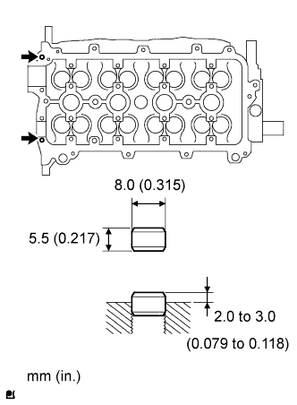
INSTALL RING WITH HEAD PIN
Using a plastic-faced hammer, tap in 2 new ring pins to the specified protrusion height.
Protrusion height:
2.0 to 3.0 mm (0.08 to 0.12 in.)
2.
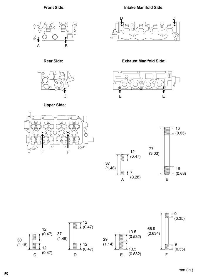
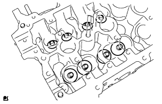
INSTALL STUD BOLT
Install the 9 stud bolts.
Torque:
Bolt A, C, F:
4.0 N*m{
41 kgf*cm
, 35 in.*lbf
}
Bolt B:
6.0 N*m{
61 kgf*cm
, 53 in.*lbf
}
Bolt D, E:
5.0 N*m{
51 kgf*cm
, 44 in.*lbf
}
3.
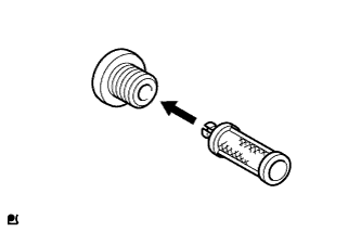
INSTALL OIL CONTROL VALVE FILTER
Install the oil control valve filter onto the with head taper screw plug.
Using an 8 mm hexagon wrench, install the with head taper screw plug and a new gasket.
Torque:
25 N*m{
250 kgf*cm
, 18 ft.*lbf
}
4.
INSTALL VALVE SPRING SEAT
Install the valve spring seats.
5.
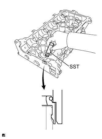
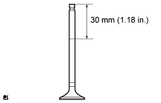
INSTALL VALVE STEM OIL SEAL
Apply a small amount of engine oil to the lip of the valve stem oil seal.
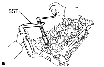
Using SST, push in a new oil seal.
SST
09201-41020
6.
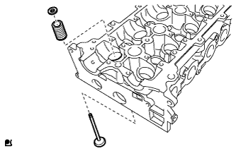
INSTALL INTAKE VALVE
Apply a light coat of engine oil to the valve stem.
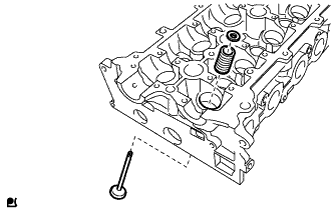
Install the inner compression spring, valve spring retainer and intake valve.
NOTICE:
Reinstall the parts in their original locations in the original order.
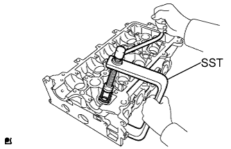
Using SST, compress the inner compression spring and place the 2 valve spring retainer locks around valve stem.
SST
09202-70020
(09202-00010)
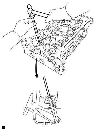
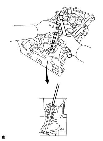
Using a plastic-faced hammer and a 5 mm (0.20 in.) pin punch with its tip wrapped in protective tape, gently tap the valve stem tip to ensure a proper fit.
NOTICE:
Do not damage the valve stem tip.
7.
INSTALL EXHAUST VALVE
Apply a light coat of engine oil to the valve stem.
Install the inner compression spring, valve spring retainer and intake valve.
NOTICE:
Install the parts in their original locations in the original order.
Using SST, compress the inner compression spring and place the 2 valve spring retainer locks around valve stem.
SST
09202-70020
(09202-00010)
Using a plastic-faced hammer and a 5 mm (0.20 in.) pin punch with its tip wrapped in protective tape, gently tap the valve stem tip to ensure a proper fit.
NOTICE:
Do not damage the valve stem tip.
8.
INSTALL VALVE LIFTER
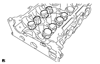
Apply a light coat of engine oil to the valve lifter.
Install the valve lifter.
Check that the valve lifter rotates smoothly by hand.