Power Heater Switch Circuit
Circuit diagnosis · Vehicles built from Nov 2005
DESCRIPTION
When the power heater switch is turned on, the power heater ECU (combustion heater assembly) sends a drive signal to the heater fuel pump. The combustion heater assembly then receives fuel necessary for combustion and starts operating.WIRING DIAGRAM
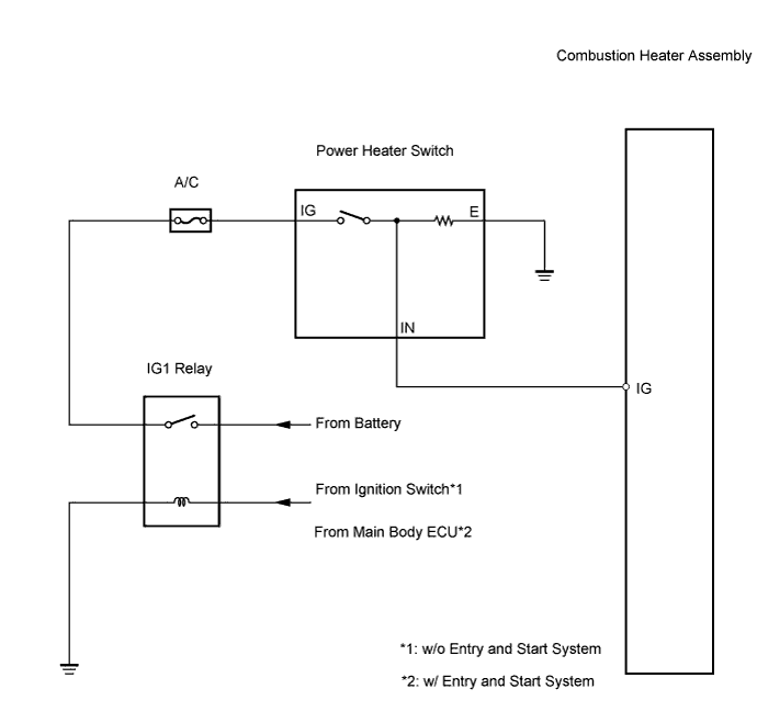

INSPECTION PROCEDURE
| 1. INSPECT POWER HEATER SWITCH |

Measure the resistance.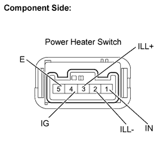
Remove the power heater switch.
Measure the resistance.
- Standard resistance:
Tester connection
Condition
Specified condition
4 (IG) - 1 (IN)
Power heater switch: ON
Below 1 Ω
4 (IG) - 1 (IN)
Power heater switch: OFF
10 kΩ or higher
Check that the power heater switch operation indicator comes on.
Connect the positive (+) lead from the battery to terminal 1 (IN) and the negative (-) lead to terminal 5 (E), and check that the operation indicator comes on.
- OK:
- Indicator comes on.
Check that the power heater switch illumination comes on.
Connect the positive (+) lead from the battery to terminal 3 (ILL+) and the negative (-) lead to terminal 2 (ILL-), and check that the switch illumination comes on.
- OK:
- Illumination comes on.
Reinstall the power heater switch.
|
|
||||

| OK | |
 |
| 2. CHECK HARNESS AND CONNECTOR (POWER HEATER ECU (COMBUSTION HEATER ASSEMBLY) - BATTERY) |
Remove the power heater ECU (combustion heater assembly).
Disconnect the A52 connector from the power heater ECU (combustion heater assembly).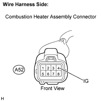
Measure the voltage.
- Standard voltage:
Tester connection
Condition
Specified condition
A52-3 (IG) - Body ground
Ignition Switch: on (IG)
Power heater switch: ON
10 to 14 V
A52-3 (IG) - Body ground
Ignition Switch: on (IG)
Power heater switch: OFF
Below 1 V
|
|
||||
| OK | |
|
| 3. CHECK HARNESS AND CONNECTOR (POWER HEATER SWITCH - BODY GROUND) |
Disconnect the D80 connector from the power heater switch.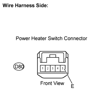
Measure the resistance.
- Standard resistance:
Tester connection
Specified condition
D80-5 (E) - Body ground
Below 1 Ω
|
|
||||
| OK | ||
 |
||
| ||