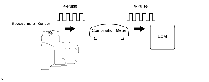
DTC P0500 Vehicle Speed Sensor "A" |
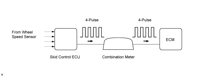
| DTC No. | DTC Detection Conditions | Trouble Areas |
| P0500 | While vehicle being driven, no vehicle speed sensor signal to ECM. (1 trip detection logic: Automatic transaxle) (2 trip detection logic: Manual transaxle) |
|
| 1.CHECK OPERATION OF SPEEDOMETER |
Drive the vehicle and check whether the operation of the speedometer in the combination meter is normal.
|
| ||||
| OK | |
 |
| 2.READ VALUE USING INTELLIGENT TESTER (VEHICLE SPEED) |
Connect the intelligent tester to the DLC3.
Turn the ignition switch to ON and turn the tester on.
Enter the following menus: Powertrain / Engine and ECT / Data List / Vehicle Speed.
Drive the vehicle.
Read the value displayed on the tester.
|
| ||||
| OK | ||
 | ||
| ||
| 3.CHECK HARNESS AND CONNECTOR (COMBINATION METER ASSEMBLY - ECM) |
Disconnect the combination meter assembly connector.
Disconnect the ECM connector.
Measure the resistance according to the value(s) in the table below.
| Tester Connection | Condition | Specified Condition |
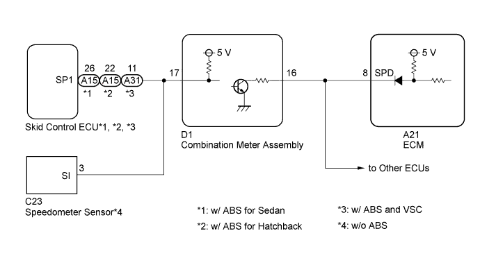
| D1-16 - A21-8 (SPD) | Always | Below 1 Ω |
| D1-16 or A21-8 (SPD) - Body ground | Always | 10 kΩ or higher |
|
| ||||
| OK | |
|
| 4.CHECK COMBINATION METER ASSEMBLY (VOLTAGE) |
 |
Disconnect the combination meter assembly connector.
Turn the ignition switch to ON.
Measure the voltage according to the value(s) in the table below.
| Tester Connection | Condition | Specified Condition |
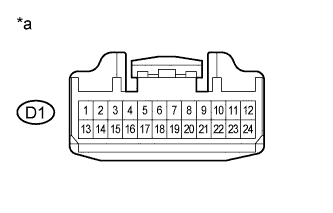
| D1-16 - Body ground | Ignition switch ON | 4.5 to 14 V |
| *a | Front view of wire harness connector (to Combination Meter Assembly) |
|
| ||||
| OK | |
|
| 5.CHECK COMBINATION METER ASSEMBLY (SPD SIGNAL OUTPUT WAVEFORM) |
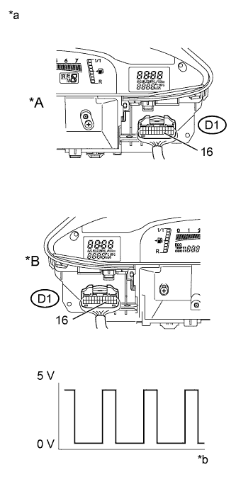 |
Move the shift lever to N (neutral).
Jack up the vehicle.
Turn the ignition switch to ON.
Check the voltage between the terminal of the combination meter and the body ground while the wheel is turned slowly.
| Tester Connection | Condition | Specified Condition |
| D1-16 - Body ground | Ignition switch ON (Turn wheel slowly) | Voltage generated intermittently |
| *A | LHD |
| *B | RHD |
| *a | Component with wire harness connected (Combination Meter Assembly) |
| *b | Turn wheel |
| Result | Proceed to |
| NG (w/ ABS) | A |
| NG (w/o ABS) | B |
| OK | C |
|
| ||||
|
| ||||
| A | |
|
| 6.CHECK COMBINATION METER ASSEMBLY (SPD SIGNAL INPUT WAVEFORM) |
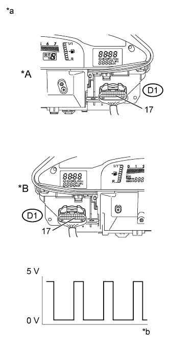 |
Move the shift lever to N (neutral).
Jack up the vehicle.
Turn the ignition switch to ON.
Check the voltage between the terminal of the combination meter and the body ground while the wheel is turned slowly.
| Tester Connection | Condition | Specified Condition |
| D1-17 - Body ground | Ignition switch ON (Turn wheel slowly) | Voltage generated intermittently |
| *A | LHD |
| *B | RHD |
| *a | Component with wire harness connected (Combination Meter Assembly) |
| *b | Turn wheel |
|
| ||||
| OK | ||
| ||
| ||
| 7.CHECK HARNESS AND CONNECTOR (COMBINATION METER ASSEMBLY - SKID CONTROL ECU) |
Check harness and connector (w/ ABS for Sedan).
Disconnect the skid control ECU connector.
Disconnect the combination meter assembly connector.
Measure the resistance according to the value(s) in the table below.
| Tester Connection | Condition | Specified Condition |
| A15-26 (SP1) - D1-17 | Always | Below 1 Ω |
| A15-26 (SP1) or D1-17 - Body ground | Always | 10 kΩ or higher |
Check harness and connector (w/ ABS for Hatchback).
Disconnect the skid control ECU connector.
Disconnect the combination meter assembly connector.
Measure the resistance according to the value(s) in the table below.
| Tester Connection | Condition | Specified Condition |
| A15-22 (SP1) - D1-17 | Always | Below 1 Ω |
| A15-22 (SP1) or D1-17 - Body ground | Always | 10 kΩ or higher |
Check harness and connector (w/ ABS and VSC).
Disconnect the skid control ECU connector.
Disconnect the combination meter assembly connector.
Measure the resistance according to the value(s) in the table below.
| Tester Connection | Condition | Specified Condition |
| A31-11 (SP1) - D1-17 | Always | Below 1 Ω |
| A31-11 (SP1) or D1-17 - Body ground | Always | 10 kΩ or higher |
|
| ||||
| OK | ||
| ||
| ||

