 |
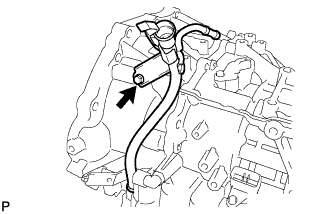
Coat a new O-ring with Toyota Genuine ATF WS, and install it onto the oil filler tube.
AUTOMATIC TRANSAXLE ASSEMBLY (for Hatchback) > INSTALLATION |
| 1. INSTALL TRANSMISSION OIL FILLER TUBE SUB-ASSEMBLY |
|
Coat a new O-ring with Toyota Genuine ATF WS, and install it onto the oil filler tube.
Install the oil filler tube onto the automatic transaxle with the bolt.
| 2. INSTALL TRANSMISSION OIL LEVEL GAUGE SUB-ASSEMBLY |
Install the oil level gauge into the transmission oil filler tube.
| 3. INSTALL NO. 2 OIL COOLER TUBE CLAMP |
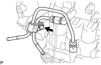 |
Provisionally install the outlet No. 1 oil cooler tube into the oil cooler tube union.
Provisionally install the inlet No. 1 oil cooler tube into the oil cooler tube union.
Install the No. 2 oil cooler tube clamp onto the transmission oil filler tube with the bolt.
| 4. INSTALL OUTLET NO. 1 OIL COOLER TUBE |
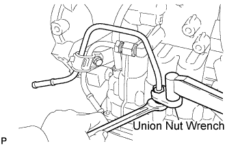 |
Using a union nut wrench, install the outlet No. 1 oil cooler tube while holding the oil cooler tube union with a wrench.
| 5. INSTALL INLET NO. 1 OIL COOLER TUBE |
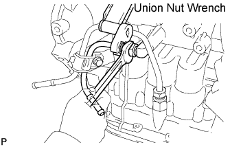 |
Using a union nut wrench, install the inlet No. 1 oil cooler tube while holding the oil cooler tube union with a wrench.
| 6. INSTALL NO. 1 TRANSMISSION CONTROL CABLE BRACKET |
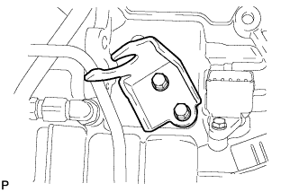 |
Install the No. 1 transmission control cable bracket onto the automatic transaxle with the 2 bolts.
| 7. INSTALL SPEEDOMETER DRIVEN HOLE COVER SUB-ASSEMBLY |
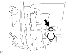 |
Coat a new O-ring with Toyota Genuine ATF WS and install it into the speedometer driven hole cover.
Install the speedometer driven hole cover onto the automatic transaxle.
| 8. INSTALL TORQUE CONVERTER ASSEMBLY |
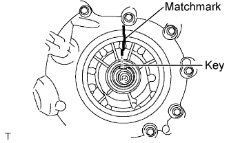 |
Set the key at the top of the front oil pump drive gear and put a mark on the housing.
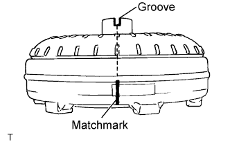 |
Put a mark on the torque converter so that its groove is clearly indicated.
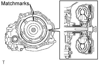 |
Align the mark on the case with the one on the torque converter and fit the spline of the input shaft to the spline of the turbine runner.
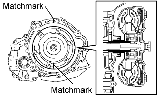 |
Rotating the torque converter, fit the spline of the stator shaft with that of the stator.
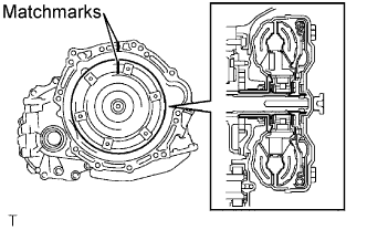 |
Rotating the torque converter, align the mark on the case with the one on the torque converter again and fit the key of the oil pump drive gear into the keyway of the torque converter.
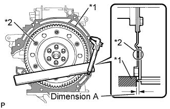 |
Using a vernier caliper and a straightedge, measure the dimension A between the automatic transaxle fitting surface (*1) of the engine and the torque converter fitting surface (*2) of the drive plate.
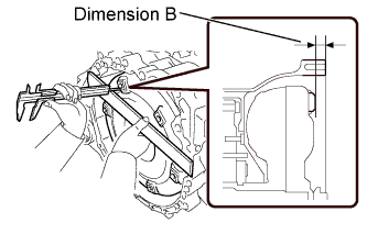 |
Using a vernier caliper and a straightedge, measure dimension B shown in the illustration and check that dimension B is greater than dimension A, which was measured in step (f).
| 9. INSTALL AUTOMATIC TRANSAXLE ASSEMBLY |
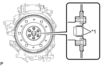 |
Apply clutch spline grease to the round of the crankshaft contact surface (*1) with the torque converter centerpiece.
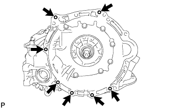 |
Install the automatic transaxle onto the engine with the 7 bolts.
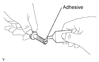 |
Remove any adhesive remaining in the 6 bolt holes of the torque converter clutch and 6 bolts.
Apply adhesive to 2 or 3 threads on the end of the 6 bolts.
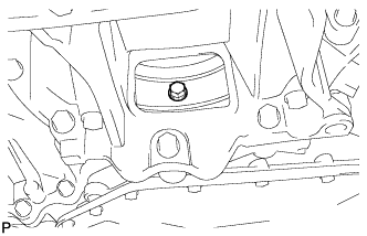 |
Install the 6 torque converter set bolts while holding the crankshaft pulley bolt with a wrench.
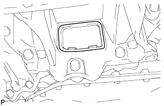 |
Install the flywheel housing under cover.
| 10. INSTALL ENGINE MOUNTING BRACKET LH |
|
Remove any adhesive remaining in the 4 bolt holes on the engine mounting bracket LH and 4 bolts.
Apply adhesive to 2 or 3 threads on the end of the 4 bolts.
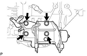 |
Install the engine mounting bracket LH to the automatic transaxle with the 4 bolts.
| 11. INSTALL ENGINE MOUNTING INSULATOR LH |
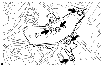 |
Install the engine mounting insulator LH with the 5 bolts.
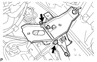 |
Install the engine mounting insulator LH and the engine mounting bracket LH with the bolt and nut.
| 12. INSTALL NO. 2 ENGINE MOVING CONTROL ROD |
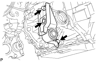 |
Install the No. 2 engine moving control rod onto the automatic transaxle with the 3 bolts.
| 13. INSTALL FRONT SUSPENSION CROSSMEMBER SUB-ASSEMBLY |
Support the front suspension crossmember with a transmission jack.
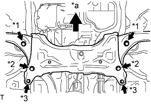 |
Provisionally install the front suspension crossmember onto the body with the 6 bolts.
| *1 | Bolt A |
| *2 | Bolt B |
| *3 | Bolt C |
| *a | Front Side |
| Bolt | Underhead Length (mm) |
| A | 38 |
| B | 99 |
| C | 41 |
By inserting SST into the datum holes in the front suspension crossmembers RH and LH alternately, tighten bolts A, B and C on both sides to the specified torque, in several steps.
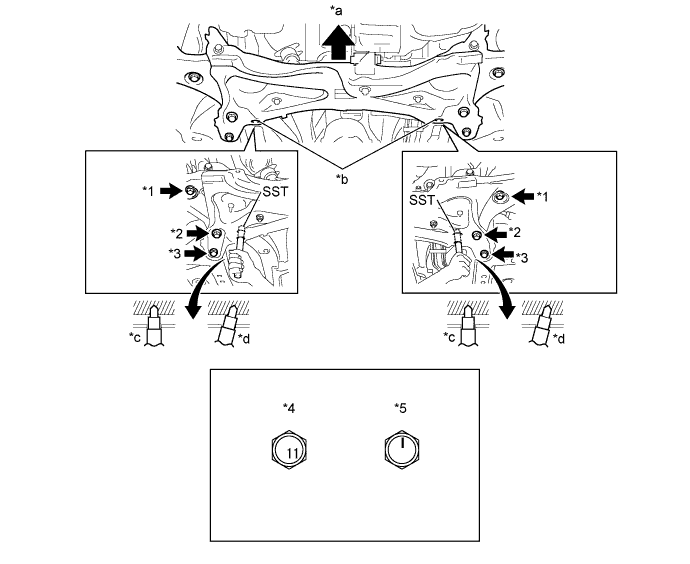
| *1 | Bolt A | *2 | Bolt B |
| *3 | Bolt C | *4 | for Bolt B with Bolt Strength Class 11T |
| *5 | for Bolt B with Bolt Strength Class 10T | - | - |
| *a | Front Side | *b | Datum Hole |
| *c | OK | *d | NG |
Install the engine moving control rod with the bolt.
| 14. INSTALL OIL COOLER HOSE |
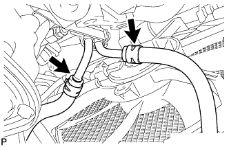 |
Install the inlet oil cooler hose onto the inlet No. 1 oil cooler tube.
Install the outlet oil cooler hose onto the outlet No. 1 oil cooler tube.
| 15. INSTALL FRONT DRIVE SHAFT ASSEMBLY LH |
for Automatic Transaxle:
Coat the spline of the inboard joint with ATF.
for Manual Transaxle:
Coat the spline of the inboard joint with gear oil.
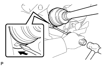 |
Align the inboard joint splines and install the drive shaft with a screwdriver and hammer.
| 16. INSTALL FRONT DRIVE SHAFT ASSEMBLY RH |
| 17. INSTALL FRONT AXLE ASSEMBLY LH |
Push the front axle out of the vehicle to align the spline of the drive shaft with the front axle and insert the front axle.
| 18. INSTALL FRONT AXLE ASSEMBLY RH |
| 19. INSTALL FRONT SUSPENSION LOWER ARM LH |
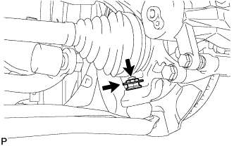 |
Install the lower arm onto the steering knuckle with a new castle nut.
Install a new clip.
| 20. INSTALL FRONT SUSPENSION LOWER ARM RH |
| 21. INSTALL TIE ROD END SUB-ASSEMBLY LH |
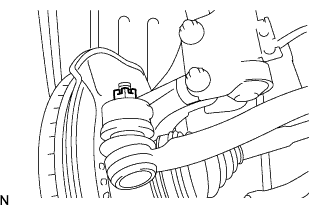 |
Install the tie rod end onto the steering knuckle with a new castle nut.
Install a new cotter pin.
| 22. INSTALL TIE ROD END SUB-ASSEMBLY RH |
| 23. INSTALL FRONT STABILIZER LINK ASSEMBLY LH |
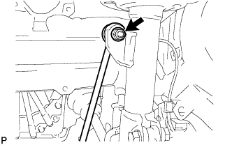 |
Install the stabilizer link with the nut.
| 24. INSTALL FRONT STABILIZER LINK ASSEMBLY RH |
| 25. INSTALL FRONT SPEED SENSOR LH |
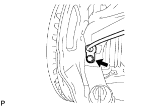 |
Install the speed sensor onto the steering knuckle with the bolt.
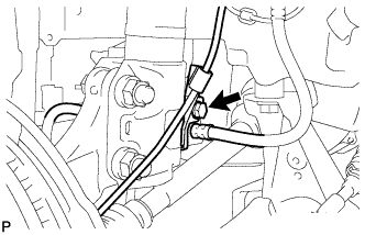 |
Install the flexible hose and speed sensor with the bolt.
| 26. INSTALL FRONT SPEED SENSOR RH |
| 27. INSTALL FRONT AXLE HUB NUT LH |
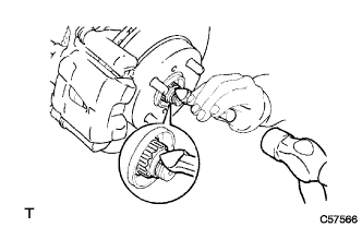 |
Using a 30 mm socket wrench, install a new axle hub nut.
Using a chisel and hammer, stake the axle hub nut.
| 28. INSTALL FRONT AXLE HUB NUT RH |
| 29. INSTALL STARTER ASSEMBLY |
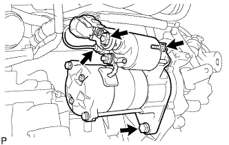 |
Install the starter assembly with the 2 bolts.
Connect the connector.
Connect terminal 30 with the nut.
Close the terminal cap.
| 30. CONNECT WIRE HARNESS |
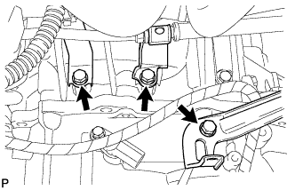 |
Install the 3 wire harness clamp brackets onto the automatic transaxle with the 3 bolts.
| 31. CONNECT CONNECTOR |
Connect the transmission revolution sensor connector.
Connect the transmission wire connector and install the clamp onto the engine mount insulator.
Connect the park/neutral position switch connector and install the clamp onto the engine mount insulator.
| 32. INSTALL NO. 3 ENGINE WIRE |
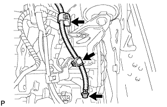 |
Install the No. 3 engine wire onto the automatic transaxle with the bolt.
Install the 2 clamps onto the engine mount insulator.
| 33. INSTALL TRANSMISSION CONTROL CABLE ASSEMBLY |
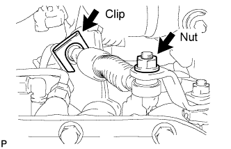 |
Install the transmission control cable onto the control shaft lever with the nut.
Install the transmission control cable into the bracket with the new clip.
| 34. INSTALL BATTERY CARRIER |
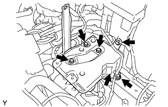 |
Install the battery carrier with the 5 bolts.
Install the clamp.
| 35. INSTALL AIR CLEANER BRACKET |
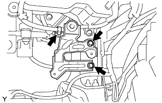 |
Install the air cleaner bracket with the 2 bolts.
Connect the wire harness clamp to the air cleaner bracket.
| 36. INSTALL AIR CLEANER ASSEMBLY |
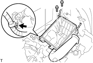 |
Install the air cleaner case with air cleaner inlet No. 1 with the 2 bolts.
Connect the wire harness to the air cleaner case.
Install the air cleaner element.
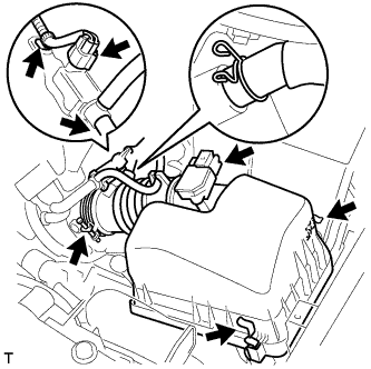 |
Install and lock the air cleaner cap and air cleaner hose and then tighten the air cleaner hose clamp.
Connect the ventilation hose to the air cleaner hose.
Connect the vacuum switching valve connector and wire harness clamp.
Connect the fuel vapor feed hose and fuel vapor feed hose No. 1 to the vacuum switching valve assembly.
Connect the intake air flow meter connector and wire harness clamp.
| 37. INSTALL NO. 2 CYLINDER HEAD COVER |
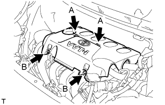 |
Tighten 2 A nuts, then 2 B nuts .
| 38. INSTALL OUTER COWL TOP PANEL (for LHD) |
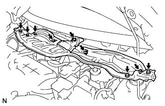 |
Install the cowl top panel with the 9 bolts.
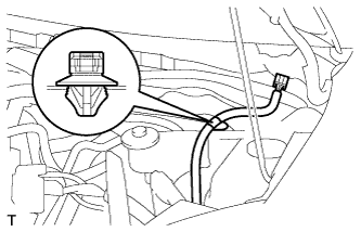 |
Connect the wire harness clamp.
| 39. INSTALL OUTER COWL TOP PANEL (for RHD) |
|
Install the cowl top panel with the 9 bolts.
|
Connect the wire harness clamp.
| 40. INSTALL NO. 2 COWL TO REGISTER DUCT SUB-ASSEMBLY (for LHD) |
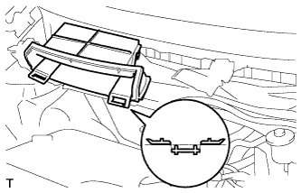 |
Engage the claw to install cowl to register duct No. 2.
| 41. REMOVE NO. 2 COWL TO REGISTER DUCT SUB-ASSEMBLY (for RHD) |
|
Engage the claw to install cowl to register duct No. 2.
| 42. INSTALL FRONT WIPER MOTOR AND LINK |
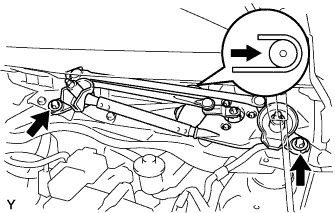 |
Connect the connector.
Slide the wiper link as shown in the illustration and engage the rubber pin with the body.
Install the front wiper motor and link with the 2 bolts.
| 43. INSTALL COWL TOP VENTILATOR LOUVER LH (for LHD) |
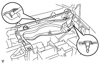 |
Engage the 4 claws and install the cowl top ventilator louver LH.
Install the 2 clips.
| 44. INSTALL COWL TOP VENTILATOR LOUVER SUB-ASSEMBLY (for LHD) |
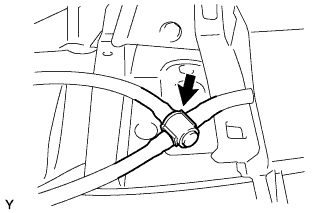 |
Connect the washer hose.
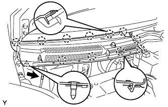 |
Engage the 11 claws and install the cowl top ventilator louver sub-assembly.
Install the clip.
Connect the washer hose.
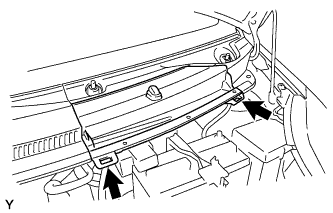 |
Engage the 2 hooks and install cowl top ventilator louver center No. 1.
| 45. INSTALL COWL TOP VENTILATOR LOUVER LH (for RHD) |
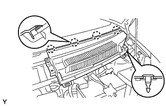 |
Engage the 4 claws and install the cowl top ventilator louver LH.
Install the clip.
| 46. INSTALL COWL TOP VENTILATOR LOUVER SUB-ASSEMBLY (for RHD) |
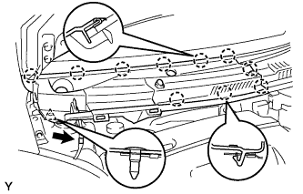 |
Engage the 10 claws and install the cowl top ventilator louver sub-assembly.
Install the clip.
Connect the washer hose.
| 47. INSTALL HOOD TO COWL TOP SEAL |
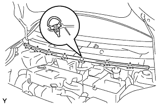 |
Engage the 7 clips and install the hood to cowl top seal.
| 48. INSTALL FRONT WIPER ARM AND BLADE ASSEMBLY LH |
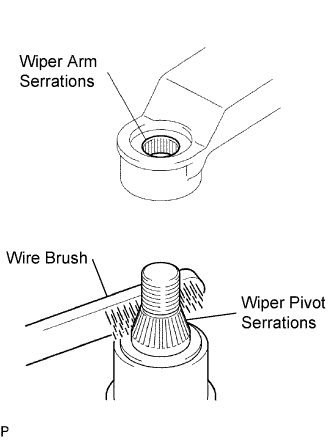 |
Scrape any metal powder off the serrated part of the wiper arm with a round file or the equivalent (when reinstalling).
Clean the wiper pivot serrations with a wire brush.
Operate the wiper, then stop the windshield wiper motor in the automatic stop position.
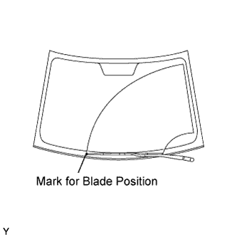 |
Align the blade tip with the mark on the windshield glass, as shown in the illustration.
Tighten the nut of the front wiper arm.
| 49. INSTALL FRONT WIPER ARM AND BLADE ASSEMBLY RH |
|
Scrape any metal powder off the serrated part of the wiper arm with a round file or the equivalent (when reinstalling).
Clean the wiper pivot serrations with a wire brush.
Operate the wiper, then stop the windshield wiper motor in the automatic stop position.
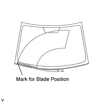 |
Align the blade tip with the mark on the windshield glass, as shown in the illustration.
Tighten the nut of the front wiper arm.
| 50. INSTALL FRONT WIPER ARM HEAD CAP |
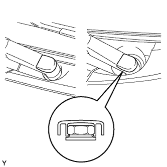 |
Engage the claw and install the 2 front wiper arm head caps.
| 51. TEMPORARILY TIGHTEN HOOD SUB-ASSEMBLY |
Provisionally install the hood with the 4 bolts.
| 52. INSPECT HOOD SUB-ASSEMBLY |
Check that the clearance measurements are within the standard ranges.
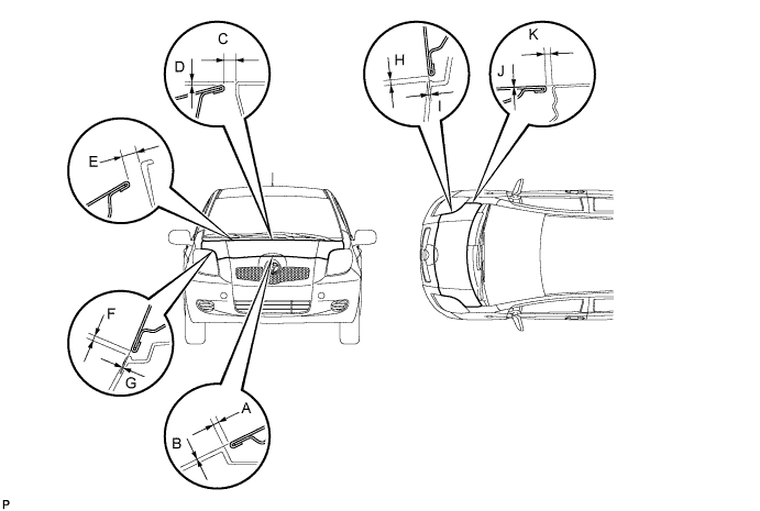
| Area | Measurement | Area | Measurement |
| A | 1.7 to 5.7 mm (0.067 to 0.224 in.) | G | -1.55 to 2.45 mm (-0.061 to 0.096 in.) |
| B | -2 to 2 mm (-0.079 to 0.079 in.) | H | 1.75 to 5.75 mm (0.067 to 0.226 in.) |
| C | 4.45 to 10.45 mm (0.175 to 0.411 in.) | I | -1.25 to 2.75 mm (-0.049 to 0.108 in.) |
| D | -0.95 to 5.05 mm (-0.037 to 0.199 in.) | J | -1.5 to 1.5 mm (-0.059 to 0.059 in.) |
| E | 7.55 to 13.55 mm (0.297 to 0.533 in.) | K | 2.0 to 5.0 mm (0.079 to 0.197 in.) |
| F | 1.65 to 5.65 mm (0.065 to 0.222 in.) | - | - |
| 53. ADJUST HOOD SUB-ASSEMBLY |
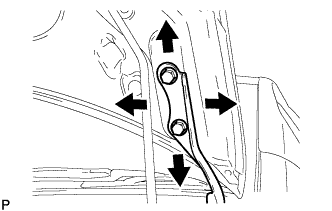 |
Loosen the hood side hinge bolts.
Move the hood to adjust the clearance to within the standard range.
Tighten the hood side hinge bolts after the adjustment.
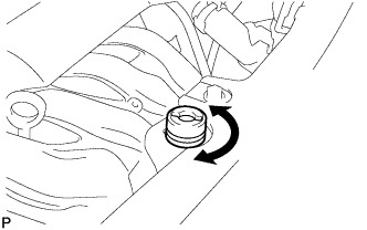 |
Adjust the height of the hood front end by turning the cushion rubber.
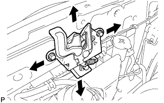 |
Adjust the hood lock.
Loosen the 3 bolts.
Adjust the hood lock position so that the striker can enter it smoothly.
Tighten the 3 bolts after the adjustment.
| 54. INSTALL FRONT WHEELS |
| 55. INSTALL NO. 1 STEERING COLUMN HOLE COVER SUB-ASSEMBLY |
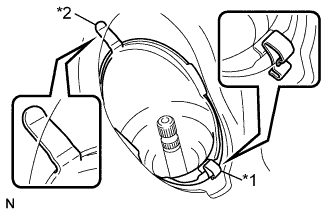 |
Install clip B onto the body portion and install No. 1 steering column hole cover onto the body portion with clip A.
| *1 | Clip A |
| *2 | Clip B |
| 56. INSTALL STEERING SLIDING YOKE SUB-ASSEMBLY |
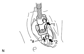 |
Align the matchmarks and install the sliding yoke onto the intermediate shaft with bolt B.
| *1 | Bolt A |
| *2 | Bolt B |
| *a | Matchmark |
Tighten bolt A.
| 57. INSTALL COLUMN HOLE COVER SILENCER SHEET |
Install the column hole cover silencer sheet with the 2 clips.
Install the floor carpet.
| 58. INSTALL BATTERY TRAY |
| 59. INSTALL BATTERY |
Install the battery onto the vehicle with the battery clamp.
Connect the cable to the battery terminal.
| 60. ADD AUTOMATIC TRANSAXLE FLUID |
| Drain and refill | 2.5 liters (2.6 US qts, 2.2 Imp. qts) |
| Dry fill | 6.4 liters (6.8 US qts, 5.6 Imp. qts) |
| 61. INSPECT AUTOMATIC TRANSAXLE FLUID LEVEL |
 |
Park the vehicle on a level surface and engage the parking brake.
With the engine idling and the brake pedal depressed, shift the shift lever into all positions from P to L, and then return it to the P position.
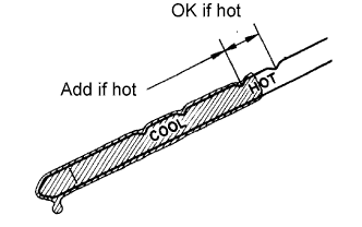
Pull out the oil level gauge and wipe it clean.
Push it fully back into the pipe.
Pull it out and check that the fluid level is within the HOT range.
If there is any leakage, repair or replace O-rings, FIPGs, oil seals, plugs or other parts.
| 62. INSPECT FOR AUTOMATIC TRANSAXLE FLUID LEAK |
| 63. INSPECT SHIFT LEVER POSITION |
When shifting the lever from P to the R position with the ignition switch on (IG) and the brake pedal depressed, make sure that the shift lever moves smoothly and moves correctly into position.
Start the engine and make sure that the vehicle moves forward when shifting the lever from N to the D position and moves rearward when shifting the lever to the R position.
If the operation cannot be performed as specified, inspect the park/neutral position switch assembly and check the shift lever assembly installation condition.
| 64. ADJUST SHIFT LEVER POSITION |
Shift the shift lever to the N position.
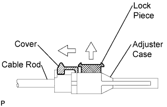 |
Slide the adjuster case cover in the direction shown in the illustration and pull out the lock piece.
Gently pull the cable rod toward the rear of the vehicle by hand to pull the cable taut.
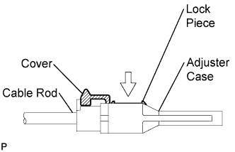 |
Press the lock piece into the adjuster case and lock it.
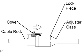 |
Slide the cover in the direction shown in the illustration.
Inspect the operation after the adjustment.
| 65. INSPECT AND ADJUST FRONT WHEEL ALIGNMENT |
Inspect and adjust the front wheel alignment (Click here).
| 66. INSTALL ENGINE UNDER COVER RH |
| 67. INSTALL ENGINE UNDER COVER LH |
| 68. CHECK ABS SENSOR SIGNAL |
Check the ABS sensor signal (Click here).
| 69. RESET MEMORY (AT initialization) |
Perform Reset Memory (AT initialization) when replacing the automatic transaxle assembly (Click here).