 |
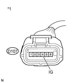
Disconnect the yaw rate and acceleration sensor connector.
| *1 | Front view of wire harness connector (to Yaw Rate and Acceleration Sensor) |
DTC C1381 Acceleration Sensor Power Supply Voltage Malfunction |
| DTC Code | DTC Detection Condition | Trouble Area |
| C1381 | At a vehicle speed of more than 3 km/h (2 mph), the acceleration sensor power source malfunction signal is received for 10 seconds or more. |
|
| 1.INSPECT YAW RATE AND ACCELERATION SENSOR (IG TERMINAL) |
|
Disconnect the yaw rate and acceleration sensor connector.
| *1 | Front view of wire harness connector (to Yaw Rate and Acceleration Sensor) |
Turn the ignition switch to ON.
Measure the voltage according to the value(s) in the table below.
| Tester Connection | Switch Condition | Specified Condition |
| D107-4 (IG) - Body ground | Ignition switch ON | 11 to 14 V |
|
| ||||
| OK | |
 |
| 2.INSPECT YAW RATE AND ACCELERATION SENSOR (GND TERMINAL) |
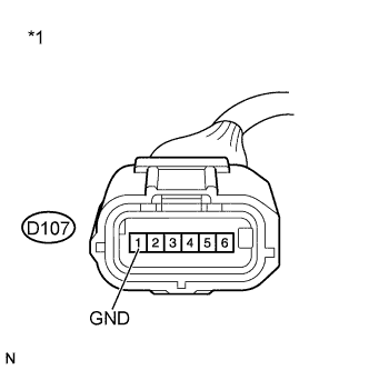 |
Turn the ignition switch off.
| *1 | Front view of wire harness connector (to Yaw Rate and Acceleration Sensor) |
Measure the resistance according to the value(s) in the table below.
| Tester Connection | Condition | Specified Condition |
| D107-1 (GND) - Body ground | Always | Below 1 Ω |
|
| ||||
| OK | |
|
| 3.RECONFIRM DTC |
Reconnect the yaw rate and acceleration sensor connector.
Clear the DTC (Click here).
Start the engine.
Perform a road test.
Check if the same DTC is recorded (Click here).
| Result | Proceed to |
| DTC (C1381) is not output | A |
| DTC (C1381) is output (for Sedan) | B |
| DTC (C1381) is output (for Hatchback) | C |
|
| ||||
|
| ||||
| A | ||
 | ||
| ||
