 |
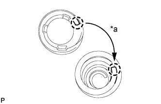
Install the rear coil spring upper insulator LH so that its gap fits onto the end of rear coil spring LH.
| *a | Fit |
REAR AXLE BEAM > INSTALLATION |
| 1. TEMPORARILY TIGHTEN REAR AXLE BEAM ASSEMBLY |
Support the rear axle beam assembly with an engine lift.
Install the rear axle beam assembly onto the vehicle and provisionally tighten the 2 bolts.
| 2. INSTALL REAR COIL SPRING LH |
Install the rear coil spring lower insulator LH onto the rear axle beam assembly.
|
Install the rear coil spring upper insulator LH so that its gap fits onto the end of rear coil spring LH.
| *a | Fit |
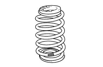 |
Install the rear coil spring LH onto the rear axle beam assembly.
 | Paint Mark |
| 3. INSTALL REAR COIL SPRING RH |
| 4. TEMPORARILY TIGHTEN REAR SHOCK ABSORBER ASSEMBLY LH |
Support the rear axle beam with a jack. Insert a wooden block between the jack and the rear axle spring seat to prevent damage.
Jack up the rear axle beam slowly, and provisionally install the rear shock absorber assembly (lower side) with the bolt and nut onto the rear axle beam assembly.
Install the suspension rear support and rear shock absorber cushion retainer.
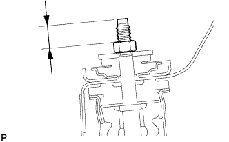 |
While holding the piston rod, install a new nut (lower nut) to the specified standard.
Install a new nut (upper nut) onto the lower nut.
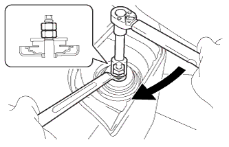 |
Hold the lower nut and tighten the upper nut against it.
| 5. TEMPORARILY TIGHTEN REAR SHOCK ABSORBER ASSEMBLY RH |
| 6. INSTALL REAR AXLE HUB AND BEARING ASSEMBLY |
Install the axle hub and bearing onto the axle beam with the 4 bolts.
| 7. INSPECT REAR AXLE HUB BEARING BACKLASH |
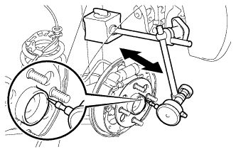 |
Using a dial indicator, check the backlash near the center of the axle hub.
| 8. INSPECT REAR AXLE HUB RUNOUT |
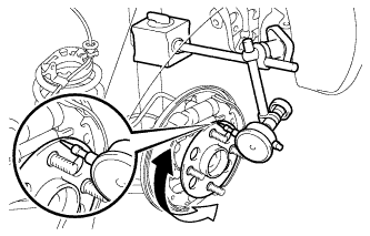 |
Using a dial indicator, check the runout of the surface of the axle hub.
| 9. INSTALL REAR BRAKE DRUM SUB-ASSEMBLY |
| 10. INSTALL NO. 3 PARKING BRAKE CABLE ASSEMBLY |
Install the No. 3 parking brake cable assembly with the bolt and a new clamp.
| 11. INSTALL NO. 2 PARKING BRAKE CABLE ASSEMBLY |
| 12. INSTALL NO. 4 REAR BRAKE TUBE |
Install the No. 4 rear brake tube onto the rear axle beam assembly with the nut.
Connect the rear flexible hose LH to the rear axle beam assembly with a new clip.
Using a union nut wrench (10 mm), install the No. 4 rear brake tube to the rear flexible hose LH while holding the rear flexible hose LH with a wrench.
| 13. INSTALL NO. 3 REAR BRAKE TUBE |
| 14. INSTALL SKID CONTROL SENSOR WIRE LH (w/ ABS) |
Install the skid control sensor wire LH onto the rear axle beam assembly with the nut.
Connect the skid control sensor wire LH connector.
| 15. INSTALL SKID CONTROL SENSOR WIRE RH (w/ ABS) |
| 16. INSTALL REAR WHEEL |
| 17. STABILIZE SUSPENSION |
Lower the vehicle from the jack.
Bounce the vehicle up and down several times to stabilize the suspension.
| 18. FULLY TIGHTEN REAR AXLE BEAM ASSEMBLY |
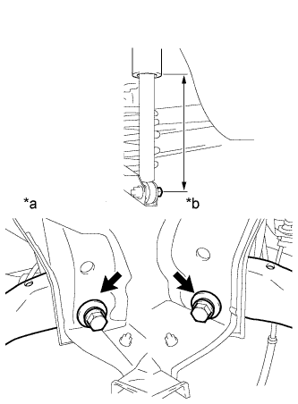 |
Suspend the jack on the rear axle spring seat and adjust the length of the rear shock absorber assembly to the reference value.
| *a | RH Side |
| *b | LH Side |
Fully tighten the 2 bolts.
| 19. FULLY TIGHTEN REAR SHOCK ABSORBER ASSEMBLY LH |
Fully tighten the rear shock absorber assembly (lower side) with the bolt.
| 20. FULLY TIGHTEN REAR SHOCK ABSORBER ASSEMBLY RH |
| 21. BLEED BRAKE LINE |
| 22. BLEED CLUTCH LINE (for Manual Transaxle) |
| 23. INSPECT REAR WHEEL ALIGNMENT |
| 24. CHECK SPEED SENSOR SIGNAL (w/ ABS) |
| 25. CHECK SPEED SENSOR SIGNAL (w/ VSC) |