 |
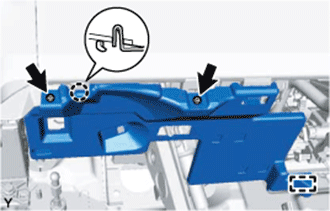
Remove the 2 <A> screws.
BRAKE BOOSTER (for LHD) > REMOVAL |
| 1. REMOVE NO. 1 INSTRUMENT PANEL UNDER COVER SUB-ASSEMBLY |
|
Remove the 2 <A> screws.
Disengage the claw and the guide and remove the instrument panel under cover.
| 2. REMOVE LOWER NO. 2 INSTRUMENT PANEL FINISH PANEL |
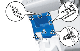 |
Disengage the 5 clips and the 2 claws and remove the instrument panel finish panel.
| 3. REMOVE LOWER INSTRUMENT PANEL FINISH PANEL |
for LHD:
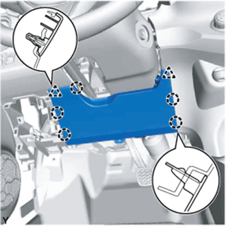 |
Disengage the 2 clips and the 5 claws and remove the instrument panel finish panel.
for RHD:
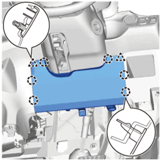 |
Disengage the 2 clips and the 6 claws and remove the instrument panel finish panel.
| 4. REMOVE WINDSHIELD WIPER MOTOR ASSEMBLY |
| 5. REMOVE BRAKE MASTER CYLINDER SUB-ASSEMBLY |
| 6. REMOVE PROPORTIONING VALVE ASSEMBLY (w/o ABS) |
| 7. REMOVE BRAKE ACTUATOR ASSEMBLY (w/ ABS) |
| 8. REMOVE FRONT NO. 1 VENTILATOR SEAL |
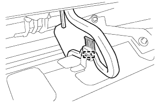 |
Disengage the clamp and remove the front No. 1 ventilator seal.
| 9. REMOVE FRONT AIR SHUTTER SEAL RH |
| 10. REMOVE INNER COWL TOP TO COWL BRACE |
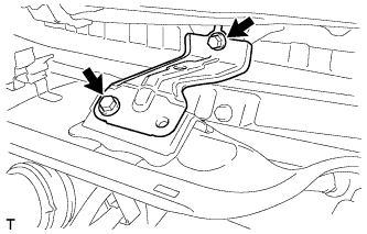 |
Remove the 2 bolts and the inner cowl top to cowl brace.
| 11. REMOVE OUTER COWL TOP PANEL |
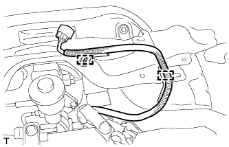 |
Disengage the 2 clamps and separate the wire harness.
Remove the 8 bolts and the outer cowl top panel.
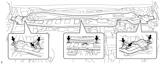
| 12. SEPARATE BRAKE MASTER CYLINDER PUSH ROD CLEVIS |
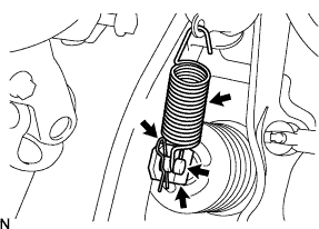 |
Remove the brake pedal return spring.
Loosen the push rod clevis lock nut.
Remove the clip and push rod pin and separate the push rod clevis from the brake pedal.
Remove the push rod clevis and push rod lock nut from the brake booster assembly.
| 13. SEPARATE NO. 2 STEERING INTERMEDIATE SHAFT ASSEMBLY |
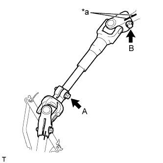 |
Place matchmarks on the No. 2 steering intermediate shaft assembly and steering column assembly.
| *a | Matchmark |
Loosen bolt A.
Remove bolt B and separate the No. 2 steering intermediate shaft assembly from the steering column assembly.
| 14. REMOVE BRAKE BOOSTER ASSEMBLY |
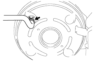 |
Slide the clip and disconnect the vacuum hose from the check valve.
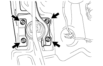 |
Remove the 4 nuts and brake booster assembly.
Remove the gasket from the brake booster assembly.